Inflight ice detection system

a technology of ice detection system and inflight detection, which is applied in the direction of de-icing equipment, aircraft components, instruments, etc., can solve the problems of affecting the performance characteristics of aircraft, affecting the performance of aircraft, and altering the handling characteristics of aircraft, so as to reduce the work load of pilots, reduce the effect of water discrimination and low cos

Inactive Publication Date: 2008-05-13
SWAN INT SENSORS
View PDF46 Cites 68 Cited by
  • Summary
  • Abstract
  • Description
  • Claims
  • Application Information

AI Technical Summary

Benefits of technology

[0018]It is an object of the present invention to provide an improved system for inflight detection of ice on the surface of an aircraft. The characteristics of such a system include simplicity, reliability, accuracy, sensitivity and effective discrimination between liquid and solid phases of water.
[0026]The present invention provides a substantial advantage over prior art and the current visual observation techniques as practiced in the industry. This system is highly sensitive in automated detection of low levels of ice accretion and provides a very effective discrimination between water and ice. The system reduces pilot work load while providing timely and accurate detection of ice during what may be a critical phase in the flight. The components of the system exposed to the external environment are passive. The present invention is simple, low cost and reliable in nature.

Problems solved by technology

Accretion of ice on the surface of aircraft is a problem experienced by flight operations.
Such ice accretion may dramatically impact the performance characteristics of the aircraft and has been known as the root cause of a number of major accidents in recent times.
Ice accretion on an aircraft surface increases drag, alters aircraft handling characteristics, disrupts the airflow, reduces lift and may result in a stall condition.
Such systems are expensive, consume considerable power and occupy significant space in the aircraft.
The pilot incurs a substantial distraction when required to make such observations.
Such an observation and related distraction may occur at a critical phase of the flight.
At the present time there are no known, reliable, un-attended and cost-effective inflight ice detection systems available for the complete range of aircraft from Transport Category to General Aviation type aircraft.
While such a system provides additional information the function of inflight icing detection does not provide a reliable detection of ice on the surface of aircraft because ice formation on the recessed surface of the probe lags ice formation on prominent aircraft surfaces.
Neither does the method provide an effective discrimination between water and ice.
Such a system requires significant set-up and is prone to changes from calibrated conditions.
Such a system is impractical for use inflight on the complete range of aircraft.
Those experienced in the art favour the use of mono-static telescope arrangement due to difficulties in maintaining critical alignment between transmit and receive optics.
While such a system may provide information on the risk of icing conditions in volumes external to the aircraft it does not provide a reliable measure for detection of inflight ice accretion on the surface of an aircraft.
While such a system, containing a single light detector is compact it cannot discriminate contamination from ice.
As the refractive index of water and ice are very similar this and other advances using refraction techniques does not have the ability to effectively discriminate between ice and water.
The use inflight of such equipment for detection of ice on aircraft surfaces is not appropriate.
Unfortunately, such equipment cannot be used in an un-attended fashion inflight.
Unfortunately, such equipment is unable to detect inflight icing conditions in an un-attended fashion.
Unfortunately, such equipment is impractical for detection of inflight icing conditions in an un-attended fashion.
While such equipment may be used inflight it's use is not accurate as in flight ice deposition can occur over a very wide range of temperature and flight conditions.
Unfortunately, in view of the randomness of ice crystal orientations, a variance will not be detected unless the sensors are set to detect at individual crystal level.
Such a system however is impracticable for use inflight on the complete range of aircraft.

Method used


Image

  • Inflight ice detection system
  • Inflight ice detection system
  • Inflight ice detection system

Examples


Embodiment Construction

[0034]The current invention detects ice accretion on aircraft surfaces by polarization discrimination technique.

[0035]The preferred embodiment and other exemplary embodiments are described below.

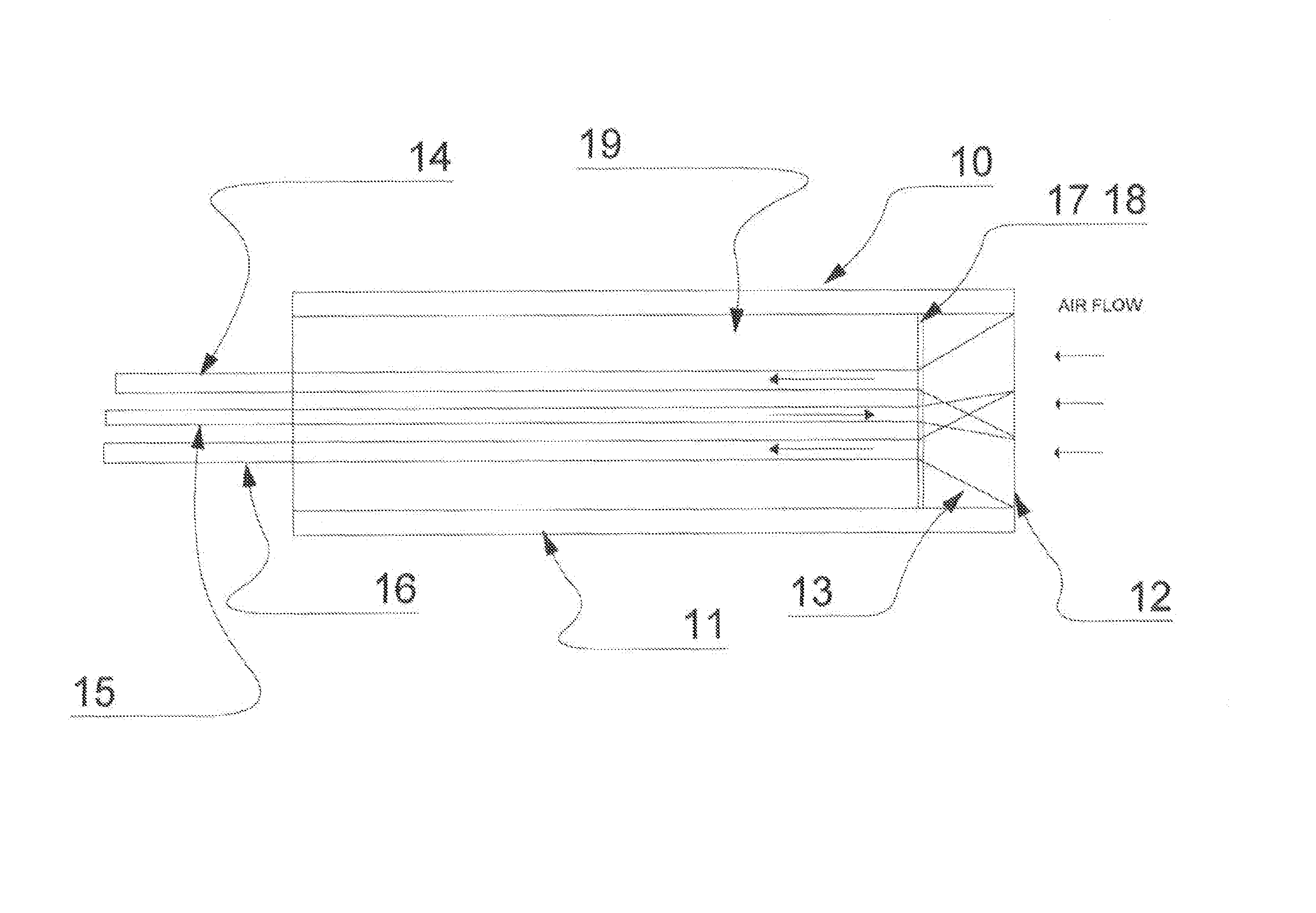
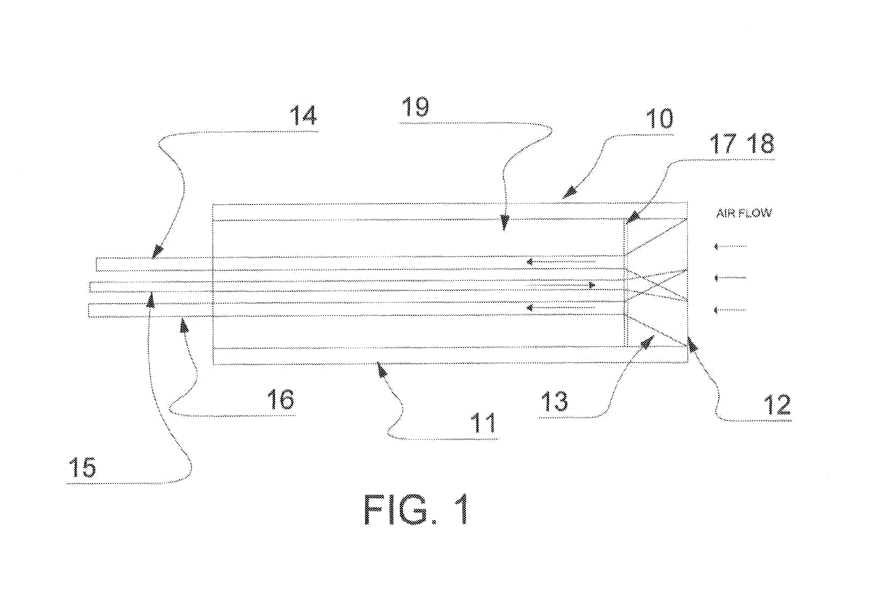
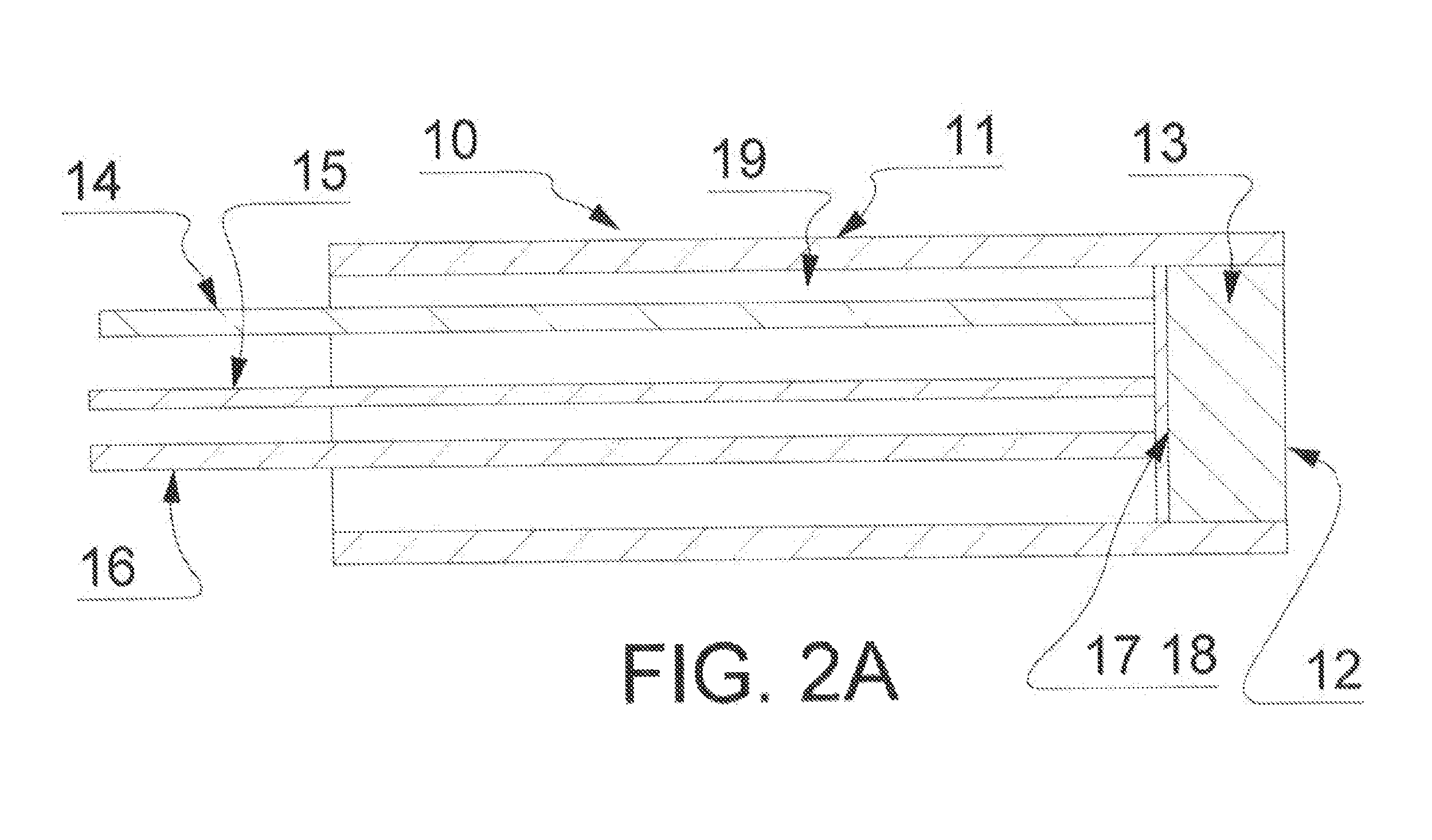
[0036]Turning initially to FIG. 1 and FIG. 2A, there is provided means for illuminating an ice collection surface 12 fixed in a housing 11 mounted on an aircraft with linearly polarized light. The illuminating light is carried by a light conductor 15 from a remote light source, and polarized through a polarising filter 17 placed between the end of the light conductor 15 and the window 13 whose outer surface is the ice collection surface 12. There is also provided means for collecting the reflected and scattered light through two larger light conductors 14 and 16 as dual receiving channels. The light conductor 14 collects light of the same polarization state as that of the illuminating light because the collected light passes through the same polarizing filter 17. The light conductor 16 colle...


PUM


Abstract

A dual channel inflight ice detection system to detect ice accretion on an aircraft surface by illuminating an ice collecting surface mounted on an aircraft with linear polarized light. The backscattered light is acquired in two light conductors one with polarization sensitivity aligned to the transmitted light and the second with polarization sensitivity orthogonal to the first. The presence of ice is determined by the change in the ratio of light intensities in the two light conductors.

Description

FIELD OF THE INVENTION[0001]The present invention relates to inflight detection of ice accretion on the surface of an aircraft.BACKGROUND OF THE INVENTION[0002]Accretion of ice on the surface of aircraft is a problem experienced by flight operations. Such ice accretion may dramatically impact the performance characteristics of the aircraft and has been known as the root cause of a number of major accidents in recent times.[0003]Accretion of ice may occur when the aircraft is flying through supercooled liquid such as cloud, rain or drizzle and at a time when the temperature of the surface of the aircraft is below freezing point. The severity of the ice accretion is dependent on the supercooled water content, the temperature and the size of the cloud droplets or raindrops. Ice accretion on an aircraft surface increases drag, alters aircraft handling characteristics, disrupts the airflow, reduces lift and may result in a stall condition.[0004]Some large Transport and Regional Aircraft ...

Claims


Application Information

Patent Timeline
Patent Type & Authority Patents(United States)
IPC IPC(8): G01W1/00
CPCB64D15/20
Inventor ZHAO, DONGANDEL, PAUL CAMERONMCGUIRE, BRIAN
Owner SWAN INT SENSORS
Why Eureka
Try Eureka