Nano-powder extraction apparatus using a hollow impeller

a technology of nano-powder and extraction apparatus, which is applied in the direction of chemistry apparatus and processes, separation processes, dispersed particle separation, etc., can solve the problems of non-reactive oxide-based materials (for example, alumina and so on) and the inability to separate nano-powder according to particle siz

Inactive Publication Date: 2008-05-13
NPC CO LTD
View PDF6 Cites 1 Cited by
  • Summary
  • Abstract
  • Description
  • Claims
  • Application Information

AI Technical Summary

Benefits of technology

[0005]Therefore, the present invention has been made in view of the above problems, and it is an object of the present invention to provide a nano-powder extraction apparatus using the rotation of hollow impellers, which is configured to extract nano-powder according to particle size thereof by effectively dissolving the nano-powder contained in plasma gas into a surfactant solution.
[0006]It is another object of the present invention to provide a nano-powder extraction apparatus which is configured to prevent the aggregation of nano-powder as the nano-powder is absorbed in and collected by a surfactant solution, thereby enabling the application of strongly reactive materials as well as non-reactive materials.
[0007]It is a further object of the present invention to provide a nano-powder extraction apparatus having upper and lower water circulating chambers installed around a tank for adjusting the interior temperature of the tank, the chambers carrying out heat transfer with the interior space of the tank, thereby increasing the separation of nano-powder according to particle size thereof.
[0008]It is yet another object of the present invention to provide a nano-powder extraction apparatus having a gas regenerating device installed at a tank for regenerating undissolved gas into cryogenic gas after collecting it and then re-supplying the cryogenic gas into the tank, thereby preventing the explosion of residual strongly reactive nano-powder existing in small quantities in the undissolved gas.

Problems solved by technology

The conventional methods as stated above, however, have a problem that it is unable to separate the nano-powder according to particle size thereof.
Another shortcoming of the conventional methods is that only non-reactive oxide-based materials (for example, alumina and so on) are applicable due to a hazard inherent in explosive reaction between colliding nano-powder particles.

Method used


Image

  • Nano-powder extraction apparatus using a hollow impeller
  • Nano-powder extraction apparatus using a hollow impeller
  • Nano-powder extraction apparatus using a hollow impeller

Examples


Embodiment Construction

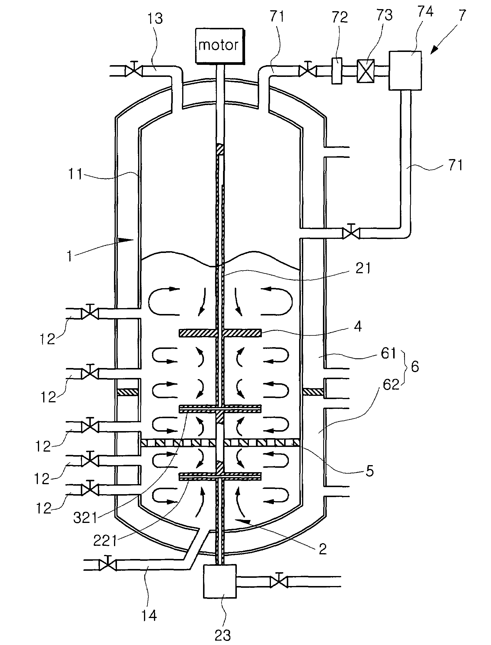
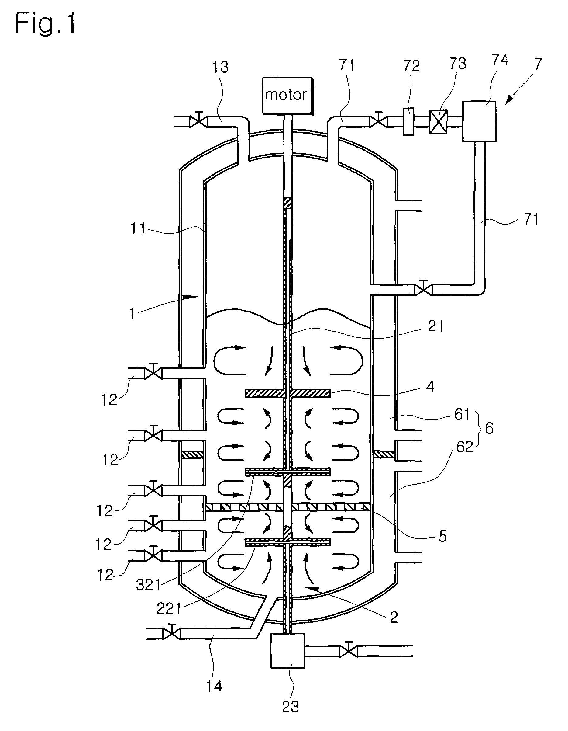
[0014]FIG. 1 is a schematic view illustrating an extraction apparatus of the present invention, and FIG. 2 is an enlarged view illustrating a rotatable drive shaft of the present invention.

[0015]An extraction apparatus of the present invention generally comprises a collecting device 1, and a gas supply device 2. The collecting device 1 includes a tank 11 charged with surfactant solution (hereinafter referred to as “solution” for ease of description). The tank 11 is provided with a plurality of powder extraction pipes 12 and solution inlet and outlet ports 13 and 14, each of the pipes and ports having respective valves. The extraction pipes 12 are arranged along the side wall of the tank 11 at different heights to extract nano-powder according to particle size thereof. The gas supply device 2 is adapted to supply plasma gas (hereinafter referred to as “gas” for ease of description) containing the nano-powder into the solution charged in the tank 11 so that the gas is uniformly distri...


PUM

PropertyMeasurementUnit
rotationaaaaaaaaaa
heightsaaaaaaaaaa
temperatureaaaaaaaaaa

Abstract

Disclosed herein is a nano-powder extraction apparatus using the rotation of a hollow impeller, which is configured to extract nano-powder according to particle size thereof by effectively dissolving the nano-powder contained in plasma gas into a surfactant solution, and to prevent the aggregation of nano-powder as the nano-powder is absorbed in and collected by a surfactant of solution, thereby enabling the application of strongly reactive materials.

Description

TECHNICAL FIELD[0001]The present invention relates generally to a nano-powder extraction apparatus using hollow impellers, and more particularly to a nano-powder extraction apparatus for extracting nano-powder using plasma by the rotation of hollow impellers, which is configured to extract the nano-powder contained in plasma gas according to particle size thereof.BACKGROUND ART[0002]Generally, in the production of nano-powder using plasma, two representative extraction methods have been employed. The first method extracts the nano-powder using a filter, and the second method extracts the nano-powder by scraping the nano-powder attached to the walls of a cryogenic container.[0003]The conventional methods as stated above, however, have a problem that it is unable to separate the nano-powder according to particle size thereof.[0004]Another shortcoming of the conventional methods is that only non-reactive oxide-based materials (for example, alumina and so on) are applicable due to a haz...

Claims


Application Information

Patent Timeline
Patent Type & Authority Patents(United States)
IPC IPC(8): B22F9/04B01D47/02B82B3/00B03B5/36
CPCB01D47/16B01D47/021B82B3/00B82Y40/00B01D47/02B03B5/36
Inventor KIM, YOUNG-NAM
Owner NPC CO LTD
Why Eureka
Try Eureka