
Equipment and process for the production of carbonated water

a production process and equipment technology, applied in the direction of machines/engines, dissolving, combustion air/fuel air treatment, etc., can solve the problem of inability to generate trouble in terms of gas addition performance, and achieve the effect of further effective production

Inactive Publication Date: 2008-05-20
MITSUBISHI RAYON CO LTD
View PDF17 Cites 13 Cited by
  • Summary
  • Abstract
  • Description
  • Claims
  • Application Information

AI Technical Summary

Benefits of technology

"The present invention provides a basic configuration for producing carbonated water using a static mixer with a high concentration of carbon dioxide gas in a short time. The configuration includes a water supplying system, a carbonic acid gas supplying system, and a static mixer with 20 to 100 elements. The water and carbonic acid gas are simultaneously supplied to the static mixer through separate pipes, allowing for efficient mixing. The carbonic acid gas is dissolved in the water to create high-concentration carbonated water. The use of a gas-liquid separator downstream of the static mixer prevents gas from causing performance issues. The concentration of carbon dioxide gas in the carbonated water can be increased by adjusting the flow rate of the gas and water supplied to the static mixer. The technical effects of this invention include efficient and high-concentration carbonated water production."

Problems solved by technology

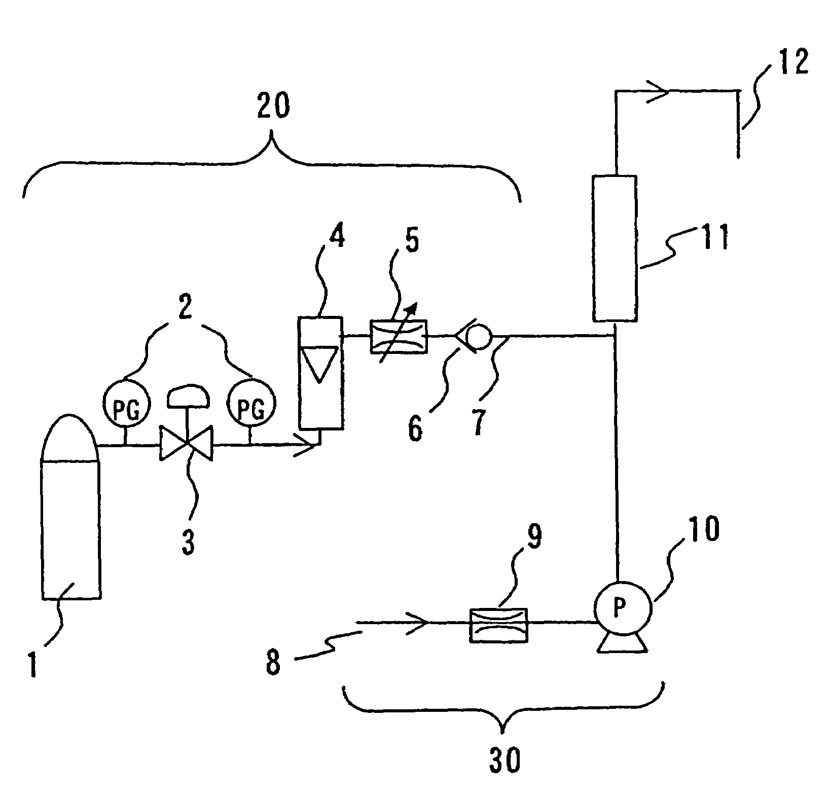
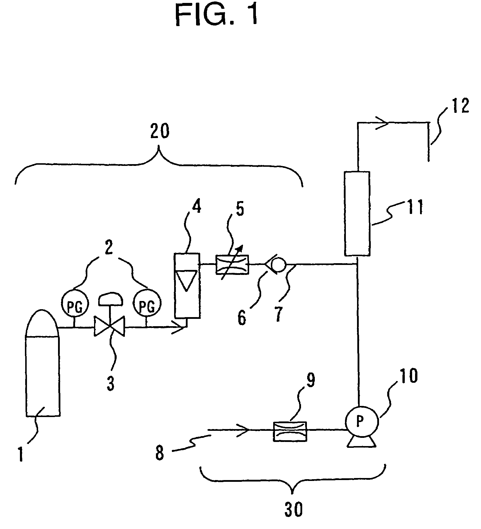
By providing the gas-liquid separator on a latter stage of the static mixer, a undissolved carbonic acid gas can be discharged outside a flow path beforehand, therefore a trouble cannot be generated in terms of a gas addition performance.

Method used


Image

  • Equipment and process for the production of carbonated water
  • Equipment and process for the production of carbonated water
  • Equipment and process for the production of carbonated water

Examples


example 1

[0077]With 200 L of hot water placed in a bath tub, carbonated water was produced using a carbonated water production equipment of the configuration shown in FIG. 6. The dissolving efficiency was calculated by a formula below:

Dissolving efficiency (%)=carbonic acid gas dissolving amount in the carbonated water / carbonic acid gas amount used ×100

[0078]Using a static mixer of the Kenix type (number of elements of 24, inner diameter 25 mm Φ), the carbonated water production equipment was operated for 20 minutes with a water supply amount of 14 (L / min) and a carbonic acid gas flow rate of 7 (L / min). At this time, a value of the Reynolds number×number of elements N of the static mixer (hereinafter, it is mentioned as Re×N) was 438,351, a number of a water circulation was 1.4 times, and furthermore, a carbonic acid gas flow rate was X (L / min) and a water flow rate was Y (L / min).

[0079]A value of a proportion X / Y of the carbonic acid gas flow rate Y with respect to the water flow rate Y (her...

example 2

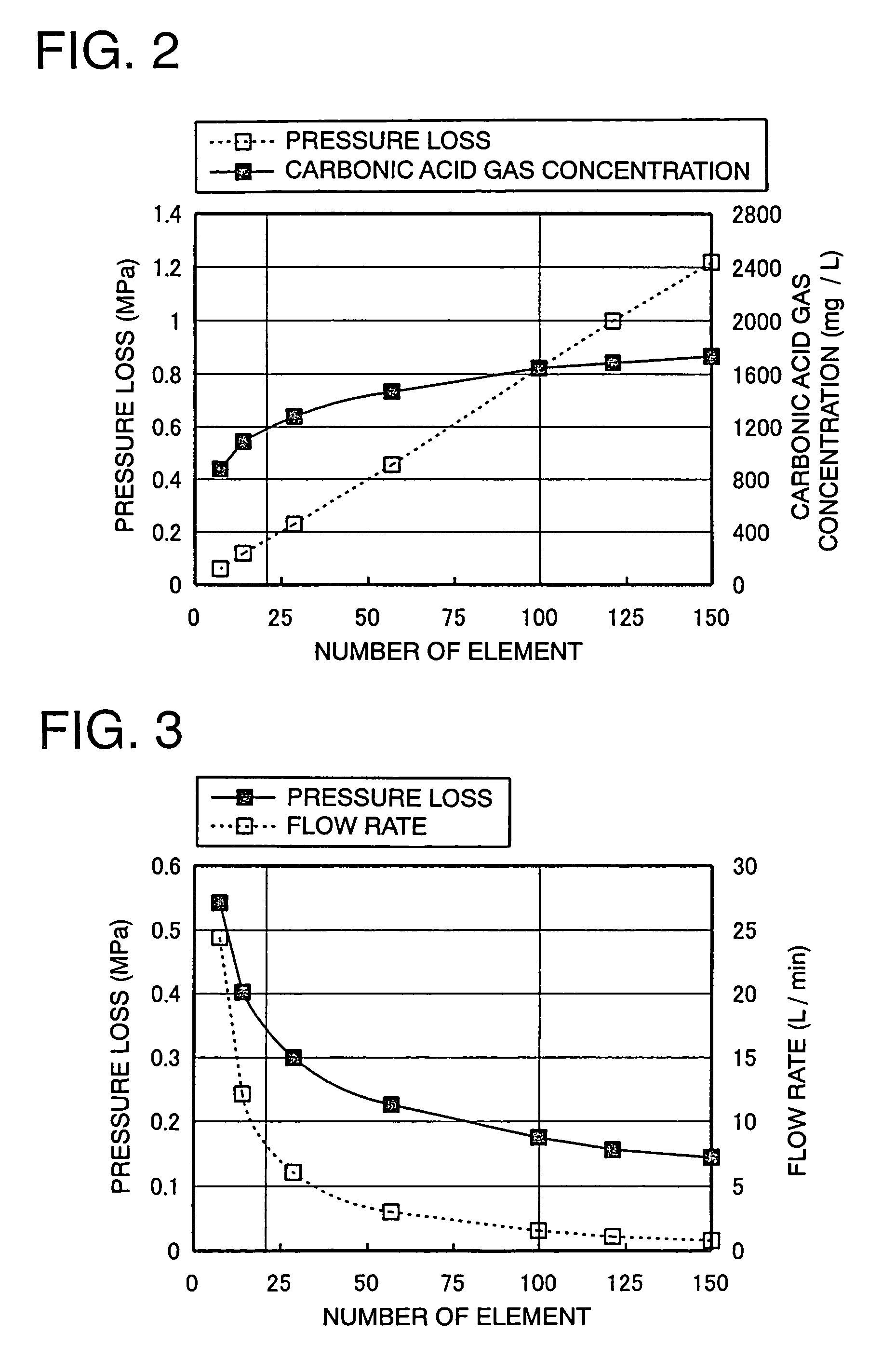
[0081]Carbonated water was produced in a same manner as in the example 1 except that the water supply amount was 16 (L / min) and the carbonic acid gas flow rate was 8 (L / min). At this time, the value Re×N was 500,972, the number of the water circulation was 1.6 times, the value X / Y was 0.5, and the pressure loss at the time of the water passage was 0.18 MPa.

[0082]The carbonic acid gas concentration of the obtained carbonated water was 1,100 (mg / L), and the dissolving efficiency was 70%.

example 3

[0083]Carbonated water was produced in a same manner as in the example 2 except that a stator type static mixer (number of elements of 28, inner diameter 23 mm Φ) was used. At this time, the value Re×N was 635,291, the number of the water circulation was 1.6 times, the value X / Y was 0.5, and the pressure loss at the time of the water passage was 0.22 MPa.

[0084]The carbonic acid gas concentration of the obtained carbonated water was 1,150 (mg / L), and the dissolving efficiency was 73%.


PUM

PropertyMeasurementUnit
concentrationaaaaaaaaaa
pressureaaaaaaaaaa

Abstract

A process for producing carbonated water having a high concentration, inexpensively and easily, involves using a static mixer having 20 to 100 elements so as to provide a value Re×N of 100,000 to 2,000,000, in with Re represents a Reynolds number, when a mixture of water and carbonic acid gas flow in the static mixer.

Description

[0001]This Application is the National Phase of International Application No. PCT / 2004 / 004453 filed Mar. 29, 2004, which designated the U.S. and was not published under PCT Article 21(2) in English, and this application claims, via the aforesaid International Application, the foreign priority benefit of and claims the priority from Japanese Application No. 2003-099184, filed Apr. 2, 2003, and from Japanese Application No. 2003-421355, filed Dec. 18, 2003, the complete disclosures of which are incorporated herein by reference.TECHNICAL FIELD[0002]The present invention relates to production equipment and a production process for carbonated water. More specifically, it relates to production equipment and a production process for carbonated water, for efficiently obtaining high-concentration carbonated water.BACKGROUND ART[0003]Since carbonated water has an excellent heat retaining effect, it has been used from the old days at a bathhouse utilizing a hot spring or the like. It is consid...

Claims


Application Information

Patent Timeline
Patent Type & Authority Patents(United States)
IPC IPC(8): B01F3/04A61H33/02B01D19/00B01F1/00B01F5/00C02F1/20
CPCB01F3/04808B01F3/04815Y10S261/07B01F23/2363B01F23/2362
Inventor OOYACHI, KENSAKAKIBARA, HIROKISUZUKI, SATOSHITASAKA, HIROSHISATOU, MASAAKI
Owner MITSUBISHI RAYON CO LTD
Learn More