
Devices and methods for preventing distal embolization during interventional procedures

Inactive Publication Date: 2008-05-20
ZOLL CIRCULATION
View PDF26 Cites 104 Cited by
  • Summary
  • Abstract
  • Description
  • Claims
  • Application Information

AI Technical Summary

Benefits of technology

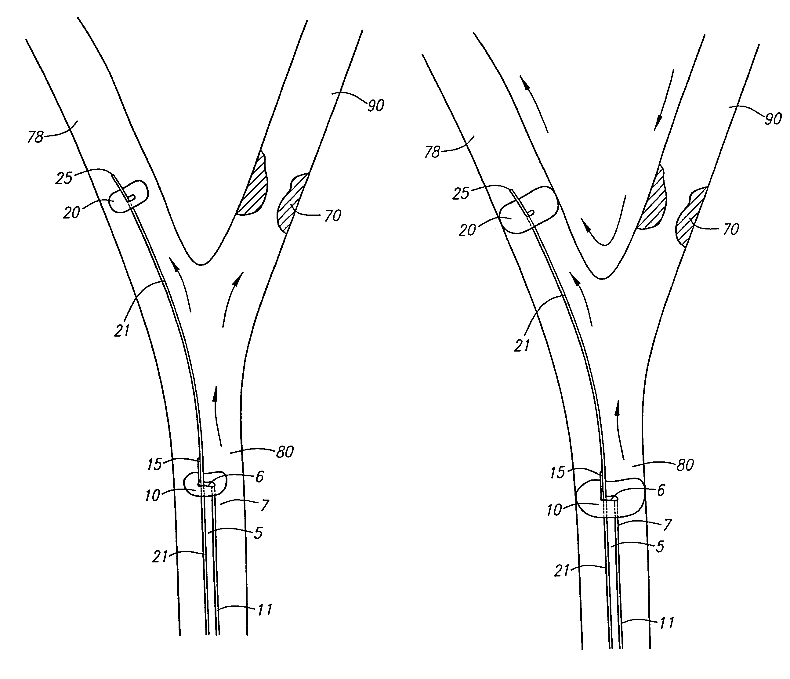
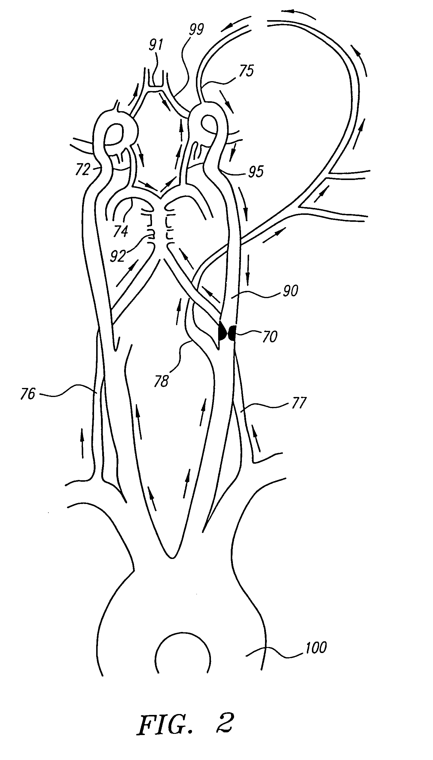
[0008]The invention provides devices and methods for preventing ischemic stroke in patients undergoing invasive carotid procedures, including angioplasty, stent placement, and / or filter insertion, by reversing blood flow down an internal carotid artery and up the ipsilateral external carotid artery. In this way, embolic debris generated as a result of placing instrumentation within a diseased carotid artery is diverted to the external carotid artery, thereby preventing stroke by minimizing distal embolization to the narrow cerebral vessels. The devices and methods are also useful to remove an embolus and improve flow (by reversing collateral blood flow across the circle of Willis) in patients with acute stroke.
[0012]In still another embodiment, a second or distal occluder includes a shunt for the passage of blood therethrough. The shunt comprises a tube having a lumen communicating with a proximal end and a distal end. A pump is operably associated with the shunt to facilitate delivery of blood from the proximal end of the shunt to the distal end of the shunt, thereby moving blood through the second occluder. The pump may be a helical screw pump included in the lumen of the shunt. The pump may be heparin coated to prevent thrombi formation.
[0015]In another method, using the device having a second occluder including a shunt for the passage of blood therethrough, the catheter is inserted in the carotid artery, with the second occluder located in the ECA and the first occluder located in the CCA. Preferably, the first occluder is expanded to occlude the CCA followed by expansion of the second occluder to occlude the ECA. Alternatively, the second occluder is expanded to occlude the ECA followed by expansion of the first occluder to occlude the CCA. A pump, traversing the ECA occluder, is activated to facilitate blood reversal from the ICA toward the ECA by moving blood through a shunt included in the second occluder. The flow rate across the second occluder in the ECA can be variably controlled by the pump.
[0016]It will be understood that there are several advantages in using the devices and methods disclosed herein for prevention of distal embolization during use of instrumentation in the carotid artery. For example, the devices (1) abolish the need for suction distal to the CCA occluder, thereby minimizing blood loss, (2) eliminate the need for systemic anticoagulation, pumping, and a second arterial or venous stick, all of which are required where suction is employed, (3) can be used to introduce a variety of diagnostic or therapeutic instrument to the carotid artery, (4) can be used in any procedures which require instrumentation within the carotid artery, (5) can be used for definitive treatment of acute or subacute ischemic stroke, (6) can be used in the angiogram or fluoroscopy suite available in most hospitals, and (7) require only one incision site for entry.

Problems solved by technology

Hemorrhagic stroke often occurs due to rupture of an aneurysm or arteriovenous malformation bleeding into the brain tissue, resulting in cerebral infarction.
Unfortunately, placing instrumentation within a diseased carotid artery is associated with increased risk of ischemic stroke, since manipulation of an atheromatous plaque in the arterial wall often causes emboli to dislodge distally in the narrow cerebral arteries.
Disadvantages associated with the conventional methods are that (1) inserting the filter through the atheromatous lesion is associated with increased risk of distal embolization, (2) using suction to reverse the flow in the internal carotid artery may increase a patient's blood loss if the suctioned blood is discarded, and (3) systemic anticoagulation and pumping may be required to recycle the suctioned blood back into the arterial or venous system, and such anticoagulation is associated with increased risk of hemorrhage.

Method used


Image

  • Devices and methods for preventing distal embolization during interventional procedures
  • Devices and methods for preventing distal embolization during interventional procedures
  • Devices and methods for preventing distal embolization during interventional procedures

Examples


Embodiment Construction

[0040]The cerebral circulation is regulated in such a way that a constant total cerebral blood flow (CBF) is generally maintained under varying conditions. For example, a reduction in flow to one part of the brain, such as in stroke, may be compensated by an increase in flow to another part, so that CBF to any one region of the brain remains unchanged. More importantly, when one part of the brain becomes ischemic due to a vascular occlusion, the brain compensates by increasing blood flow to the ischemic area through its collateral circulation via the Circle of Willis.

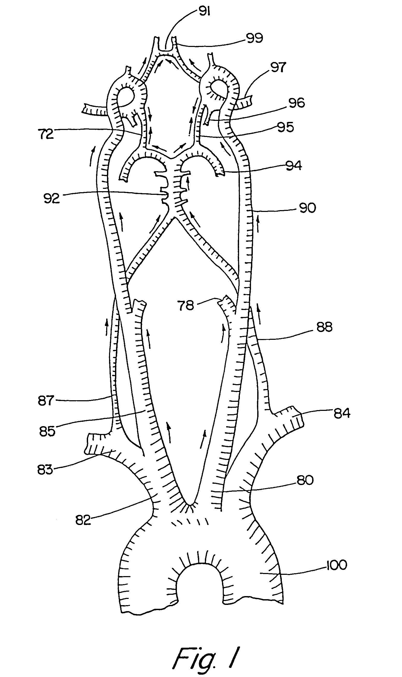
[0041]FIG. 1 depicts a normal cerebral circulation and formation of Circle of Willis. Aorta 100 gives rise to right brachiocephalic trunk 82, left common carotid artery (CCA) 80, and left subclavian artery 84. The brachiocephalic artery further branches into right common carotid artery 85 and right subclavian artery 83. The left CCA gives rise to left internal carotid artery (ICA) 90 which becomes left middle cerebral a...


PUM


Abstract

The invention provides a medical device having a catheter and first and second expandable members. The device may be used for protection against stroke by inserting the catheter into a carotid artery, locating the first expandable member within a common carotid artery, locating the second expandable member within an external carotid artery, expanding the first expandable member to occlude the common carotid artery, and expanding the second expandable member to at least partially obstruct the external carotid artery. By this method antegrade blood flow in the internal carotid artery stops.

Description

[0001]This is a continuation of U.S. application Ser. No. 09 / 909,642, filed Jul. 20, 2001, now U.S. Pat. No. 6,626,886, which is a continuation of U.S. application Ser. No. 09 / 687,150, filed Oct. 12, 2000, now U.S. Pat. No. 6,623,471, which is a continuation of U.S. application Ser. No. 09 / 287,252, filed Apr. 7, 1999, now U.S. Pat. No. 6,146,370, all of which are expressly incorporated herein by reference in their entirety.FIELD OF THE INVENTION[0002]The present invention relates generally to devices and methods useful in treating patients with stroke or occlusive cerebrovascular disease. More specifically, the invention provides an extracranial device capable of reversing flow down an internal carotid artery, and into the external carotid artery during an invasive carotid procedure, thereby avoiding distal embolization of vascular debris. Various diagnostic or therapeutic instruments, including an atherectomy catheter, a filter, and / or an angioplasty / stent catheter, can be introduc...

Claims


Application Information

Patent Timeline
IPC IPC(8): A61M31/00A61M25/00A61M29/02
CPCA61M25/104A61M2025/0003A61M2025/1015A61M2025/1052
Inventor BARBUT, DENISE R.
Owner ZOLL CIRCULATION
Learn More