Plasma arc torch having an electrode with internal passages

a technology of plasma arc torch and electrode, which is applied in the field of plasma arc torch systems and processes, can solve the problems of nozzle wear, reduced electrode life, and electrode wear over time, and achieve the effect of reducing nozzle wear and high emissivity material

Inactive Publication Date: 2008-05-20
HYPERTHERM INC
View PDF38 Cites 74 Cited by
  • Summary
  • Abstract
  • Description
  • Claims
  • Application Information

AI Technical Summary

Benefits of technology

[0010]It is therefore a principal object of this invention to reduce the nozzle wear by minimizing the deposition of high emissivity material on the nozzle during the cutting process.
[0011]Another principal object of the invention is to reduce the electrode wear by minimizing the ejection of molten emissivity material from the electrode insert.
[0012]Another principal object of the invention is to provide an electrode for a plasma arc torch that increases the axial momentum of the plasma arc column, promoting faster and better cutting performance.
[0013]Another principal object of the invention is to provide an electrode for a plasma arc torch that results in an improved cut quality.
[0014]Yet another principal object of the invention is to maintain the electrode life while reducing nozzle wear.
[0015]The present invention features, in one aspect, an improved electrode for a plasma arc cutting torch which minimizes the deposition of high emissivity material on the nozzle. In another aspect, the invention reduces electrode wear by minimizing the ejection of molten emissivity material from the electrode insert. In another aspect, the electrode increases the axial momentum of the plasma arc column, promoting faster and better cutting performance.

Problems solved by technology

In all plasma arc torches, particularly those using a reactive plasma gas, the electrode shows wear over time in the form of a generally concave pit at the exposed emission surface of the insert.
Deposition of high emissivity material on the inside surface of the nozzle during the plasma arc start and stop stages is addressed by U.S. Pat. Nos. 5,070,227 and 5,166,494, commonly assigned to Hypertherm, Inc. in Hanover, N.H. It has been found that the heretofore unsolved problem of high emissivity material deposition during the steady state of the arc not only reduces electrode life but also causes nozzle wear.
As such, a common cause of nozzle wear is undesired arc attachment to the nozzle, which melts the copper usually at the nozzle orifice.
Double arcing, i.e., an arc that jumps from the electrode to the nozzle and then from the nozzle to the workpiece, results in undesired arc attachment.
Double arcing has many known causes and results in increased nozzle wear and / or nozzle failure.
The deposition of high emissivity insert material on the nozzle also causes double arcing and shortens the nozzle life.

Method used


Image

  • Plasma arc torch having an electrode with internal passages
  • Plasma arc torch having an electrode with internal passages
  • Plasma arc torch having an electrode with internal passages

Examples


Embodiment Construction

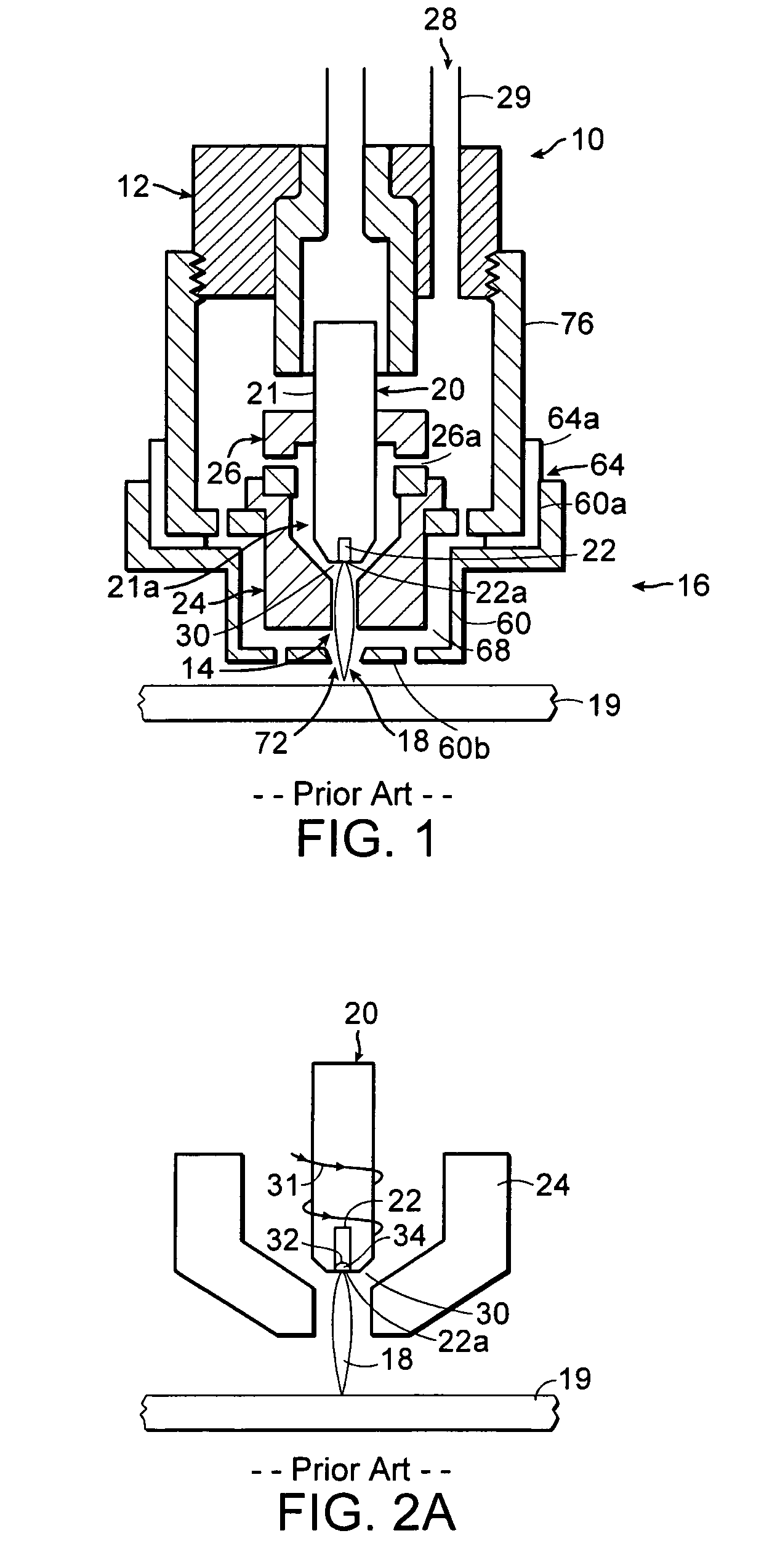
[0056]FIG. 1 illustrates in simplified schematic form of a typical plasma arc cutting torch 10 representative of any of a variety of models of torches sold by Hypertherm, Inc., with offices in Hanover, N.H. The torch 10 has a body 12 that is typically cylindrical with an exit orifice 14 at a lower end 16. A plasma arc 18, i.e., an ionized gas jet, passes through the exit orifice 14 and attaches to a workpiece 19 being cut. The torch 10 is designed to pierce and cut metal, particularly mild steel, or other materials in a transferred arc mode. In cutting mild steel, the torch 10 operates with a reactive gas, such as oxygen or air, as the plasma gas 28 to form the transferred plasma arc 18.

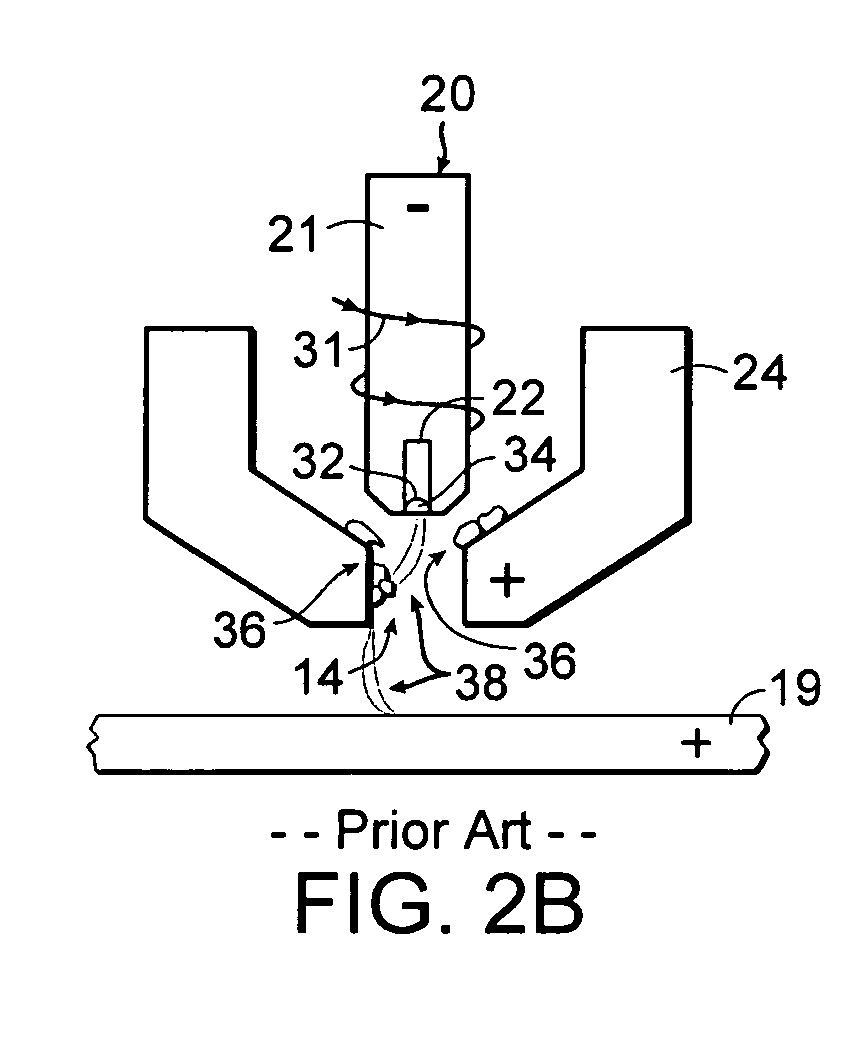
[0057]The torch body 12 supports a copper electrode 20 having a generally cylindrical body 21. A hafnium insert 22 is press fit into the lower end 21a of the electrode 20 so that a planar emission surface 22a is exposed. The torch body 12 also supports a nozzle 24 which is spaced from the electrode 2...


PUM


Abstract

An electrode for a plasma arc cutting torch which minimizes the deposition of high emissivity material on the nozzle, reduces electrode wear, and improves cut quality. The electrode has a body having a first end, a second end in a spaced relationship relative to the first end, and an outer surface extending from the first end to the second end. The body has an end face disposed at the second end. The electrode also includes at least one passage extending from a first opening in the body to a second opening in the end face.

Description

FIELD OF THE INVENTION [0001]The invention generally relates to the field of plasma arc torch systems and processes. In particular, the invention relates to an improved electrode for use in a plasma arc torch and a method of manufacturing such electrode.BACKGROUND OF THE INVENTION [0002]Material processing apparatus, such as plasma arc torches and lasers are widely used in the cutting of metallic materials. A plasma arc torch generally includes a torch body, an electrode mounted within the body, a nozzle with a central exit orifice, electrical connections, passages for cooling and arc control fluids, a swirl ring to control the fluid flow patterns, and a power supply. Gases used in the torch can be non-reactive (e.g., argon or nitrogen), or reactive (e.g., oxygen or air). The torch produces a plasma arc, which is a constricted ionized jet of a plasma gas with high temperature and high momentum.[0003]Plasma arc cutting torches produce a transferred plasma arc with a current density t...

Claims


Application Information

Patent Timeline
Patent Type & Authority Patents(United States)
IPC IPC(8): B23K9/00B23K10/00
CPCB23K10/02H05H1/34H05H2001/3436H05H2001/3442H05H2001/3478H05H1/3436H05H1/3442H05H1/3478
Inventor TWAROG, PETER J.HACKETT, CHARLES M.COOK, DAVID J.ALTOBELLI, BRUCE P.BOUTHILLIER, DAVID L.
Owner HYPERTHERM INC
Why Eureka
Try Eureka