

Analyzer
an analytical device and analyzer technology, applied in the field of analytical devices, can solve the problems of explosive hydrogen gas, difficult transportation of hydrogen generators, and inability of conventional analyzers to simply transport and handle hydrogen gas
- Summary
- Abstract
- Description
- Claims
- Application Information
AI Technical Summary
Benefits of technology
Problems solved by technology
Method used
Image

Examples
first embodiment
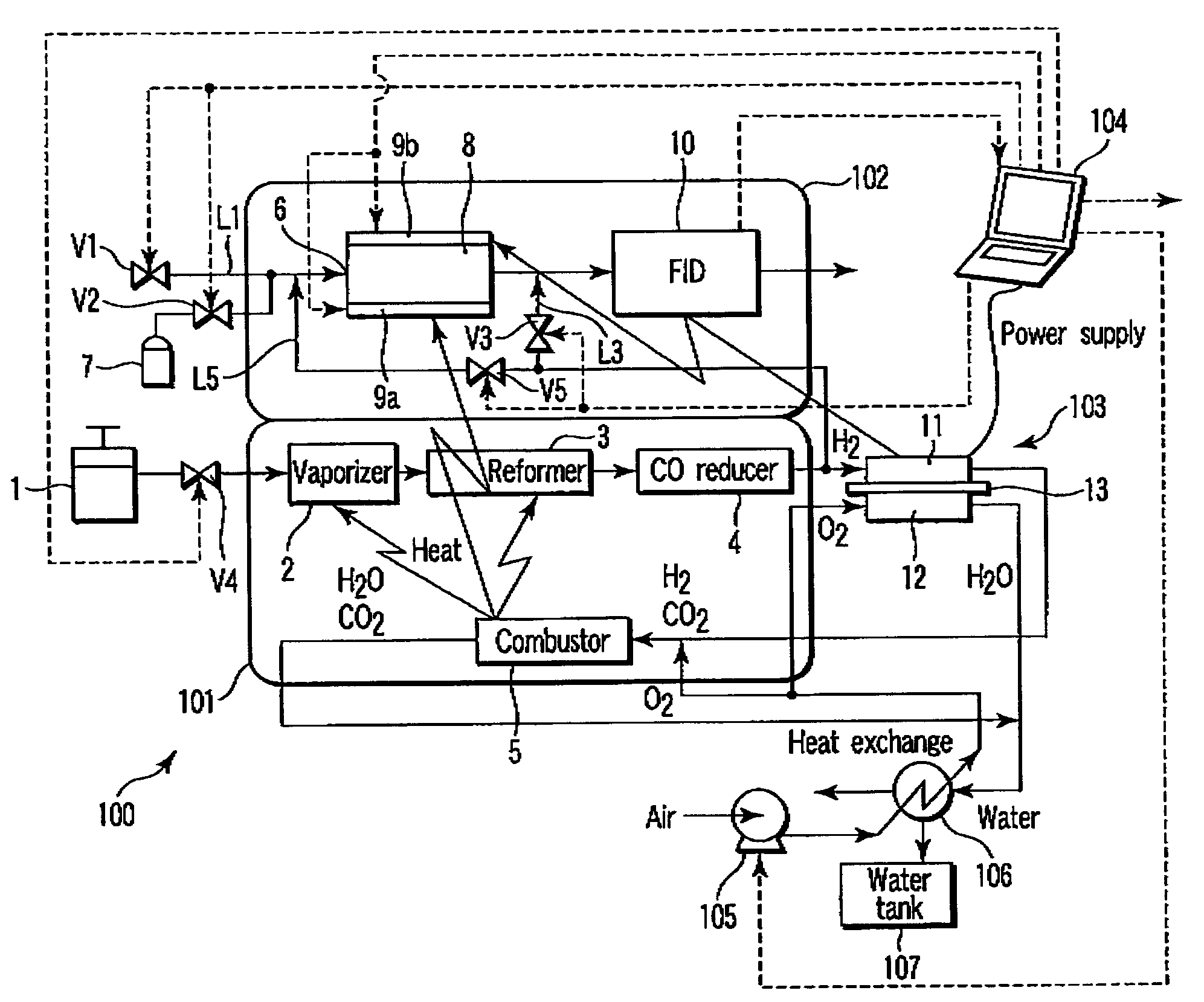
[0023]FIG. 1 is a block diagram schematically showing an analyzer according to a first embodiment of the present invention.
[0024]An analyzer 100 of the first embodiment includes a reforming unit 101, analyzing unit 102, fuel cell 103, and analysis controller 104. Hydrogen generated in the reforming unit 101 is used in the analyzing unit 102 in order to analyze a sample gas. This generated hydrogen is also used in the fuel cell 103 which generates electric power by using the hydrogen. The generated power is used in the analysis controller 104 for the purpose of analysis. More specifically, this generated power is used as at least a part of electric power necessary for the analysis controller 104 to, e.g., amplify or analyze an output signal from the analyzing unit 102. This power is also used as at least a part of electric power necessary to operate, e.g., the reforming unit 101, analyzing unit 102, or fuel cell 103.
[0025]The analyzer 100 further includes a pump 105, heat exchanger 1...
second embodiment
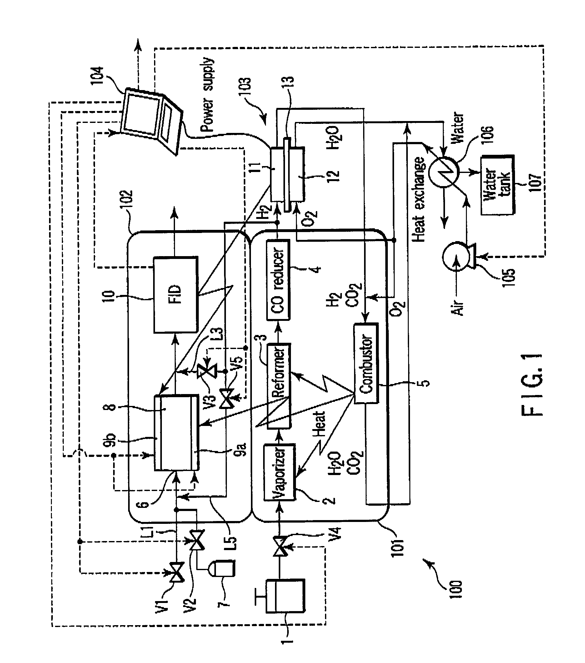
[0071]FIG. 3 is a block diagram schematically showing an analyzer according to a second embodiment of the present invention. Note that the same reference numerals as in the first embodiment shown in FIG. 1 denote the same parts, and an explanation thereof will be omitted.
[0072]An analyzer 200 of the second embodiment has an analyzing unit 201 which measures, for example, the atomic absorption spectrophotometric value. The analyzing unit 201 includes a reducing unit 21 and detector 22. The analyzing unit 201 identifies (qualitatively and / or quantitatively determines) components contained in a sample fluid in a liquid or gas state, together with an analysis controller 104. For example, the detector 22 of the analyzing unit 201 detects arsenic or antimony contained in a sample fluid such as underground water.
[0073]The reducing unit 21 reduces components contained in a sample fluid by using hydrogen contained in a reformed gas supplied from a reforming unit 101. In the reducing unit 21,...
third embodiment
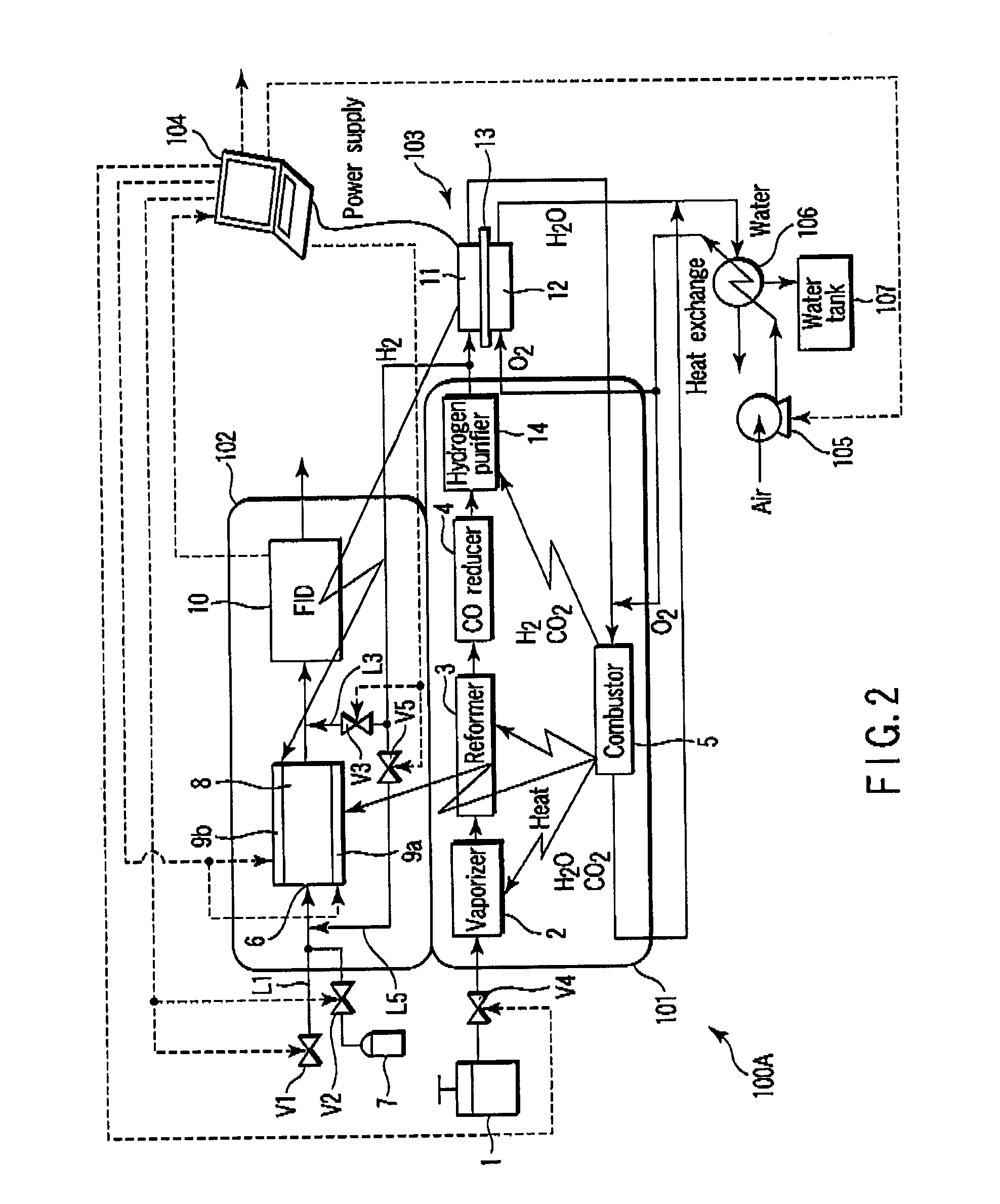
[0078]FIG. 4 is a block diagram schematically showing an analyzer according to a third embodiment of the present invention. Note that the same reference numerals as in the above embodiments denote the same parts, and an explanation thereof will be omitted.
[0079]An analyzer 300 of the third embodiment has an analyzing unit 301 which performs electrochemical measurements. The analyzing unit 301 includes an electrochemical cell 302 and electrochemical instrumentation 303. The electrochemical cell 302 includes a working electrode (WE) 31, reference electrode (RE) 32, and counter electrode (CE) 33. The working electrode (WE) 31, reference electrode (RE) 32, and counter electrode (CE) 33 are dipped in a sample liquid. The electrochemical instrumentation 303 transmits and receives signals with the working electrode (WE) 31, reference electrode (RE) 32, and counter electrode (CE) 33 of the electrochemical cell 302. The analyzing unit 301 also has a potentiostat (PS) (not shown) or a galvano...
PUM
| Property | Measurement | Unit |
|---|---|---|
| temperature | aaaaa | aaaaa |
| temperature | aaaaa | aaaaa |
| temperature | aaaaa | aaaaa |
Abstract
Description
Claims
Application Information