[0015]The present invention overcomes the disadvantages associated with treating chronic obstructive pulmonary
disease, as briefly described above, by utilizing the phenomenon of collateral ventilation to increase the expiratory flow from a diseased lung. The present invention also provides a means for assisting in or facilitating pulmonary decompression to compress the diseased area or area of the lung or lungs to a smaller volume.
[0019]The long-term
oxygen therapy system of the present invention delivers oxygen directly to diseased sites in a patient's lungs. Long term
oxygen therapy is widely accepted as the
standard treatment for hypoxia caused by chronic obstructive pulmonary disease, for example,
pulmonary emphysema.
Pulmonary emphysema is a chronic obstructive pulmonary disease wherein the alveoli of the lungs lose their elasticity and the walls between adjacent alveoli are destroyed. As more and more alveoli walls are lost, the
air exchange surface area of the lungs is reduced until
air exchange becomes seriously impaired. The combination of
mucus hypersecretion and dynamic
air compression is a mechanism of
airflow limitation in chronic obstructive pulmonary disease. Dynamic
air compression results from the loss of
tethering forces exerted on the
airway due to the reduction in
lung tissue elasticity. Essentially, stale air accumulates in the lungs, thereby depriving the individual of oxygen. Various methods may be utilized to determine the location or locations of the diseased tissue, for example, computerized axial
tomography or CAT scans,
magnetic resonance imaging or MRI,
positron emission tomograph or PET, and / or standard X-
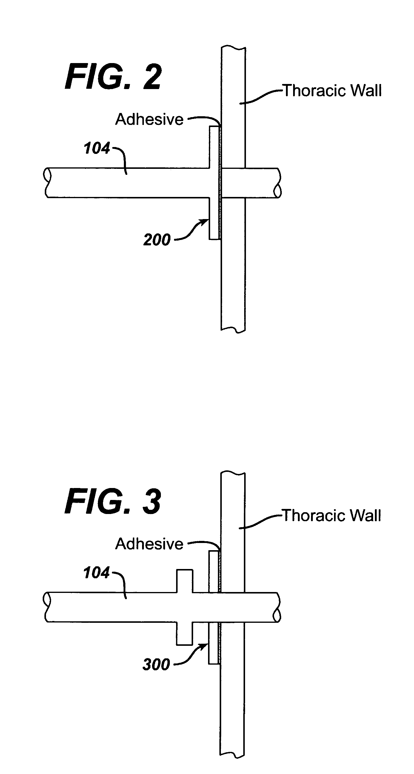
ray imaging. Once the location or locations of the diseased tissue are located, anastomotic openings are made in the
thoracic cavity and lung or lungs and one or more
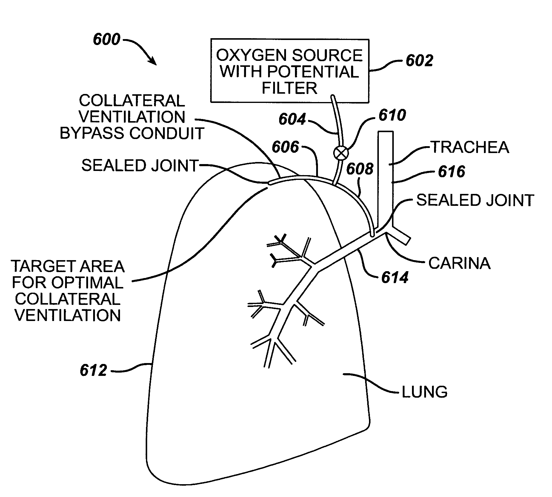
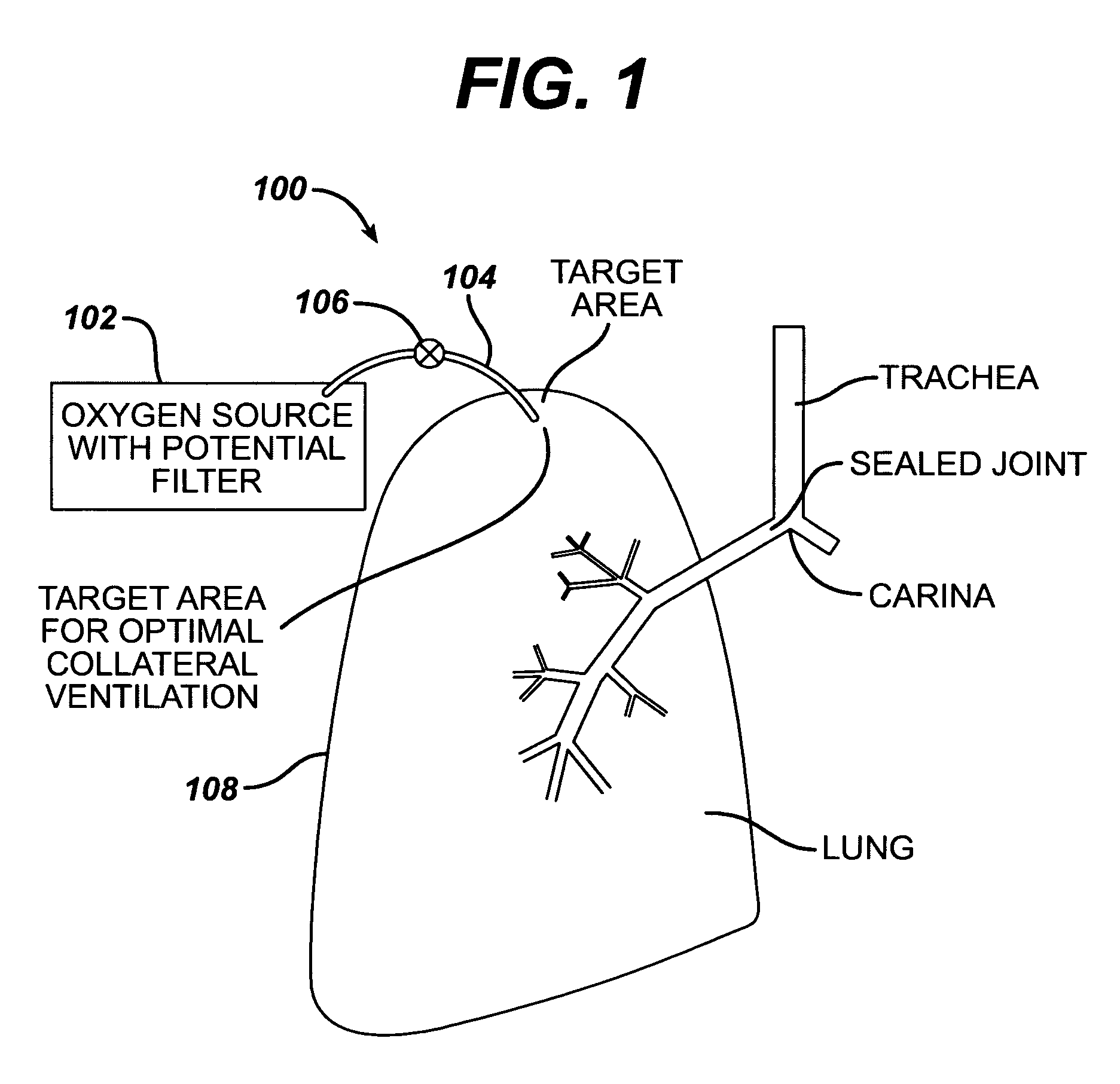
oxygen carrying conduits are positioned and sealed therein. The one or more
oxygen carrying conduits are connected to an oxygen source which supplies oxygen under elevated pressure directly to the diseased portion or portions of the lung or lungs. The pressurized oxygen essentially displaces the accumulated air and is thus more easily absorbed by the alveoli tissue. In addition, the long term
oxygen therapy system may be configured in such a way as to provide collateral ventilation bypass in addition to direct oxygen therapy. In this configuration, an additional conduit may be connected between the main conduit and the individual's trachea with the appropriate valve arrangement. In this configuration, stale air may be removed through the trachea when the individual exhales since the trachea is directly linked with the diseased site or sites in the lung via the conduits.
[0020]The long term oxygen therapy system of the present invention improves
oxygen transfer efficiency in the lungs thereby reducing
oxygen supply requirements, which in turn reduces the patient's medical costs. The system also allows for improved self-image, improved mobility, greater exercise capability and is easily maintained.
[0024]The pulmonary decompression device of the present invention removes air from hyperinflated regions of the lung or lungs of a patient by creating a slight pressure differential between the internal volume of the lung and a location external of the lung. An apparatus such as a vacuum fan or pump creates the pressure differential, thereby removing the trapped air and reducing the volume of diseased tissue.
[0025]The lung reduction device of the present invention allows trapped air from hyperinflated regions of the lung or lungs of a patient to vent to the external environment through a one-way valve. The valve prevents air from flowing back into the lung or lungs.

