Aluminum electrolytic capacitor having an anode having a uniform array of micron-sized pores

Inactive Publication Date: 2008-06-03
CATALYTIC MATERIALS
View PDF7 Cites 31 Cited by
  • Summary
  • Abstract
  • Description
  • Claims
  • Application Information

AI Technical Summary

Problems solved by technology

Unfortunately, the electrochemical etching technique generates an undesirable wide pore size distribution and it is impossible to create the desired surface architecture to gi

Method used


Image

  • Aluminum electrolytic capacitor having an anode having a uniform array of micron-sized pores
  • Aluminum electrolytic capacitor having an anode having a uniform array of micron-sized pores
  • Aluminum electrolytic capacitor having an anode having a uniform array of micron-sized pores

Examples


Embodiment Construction

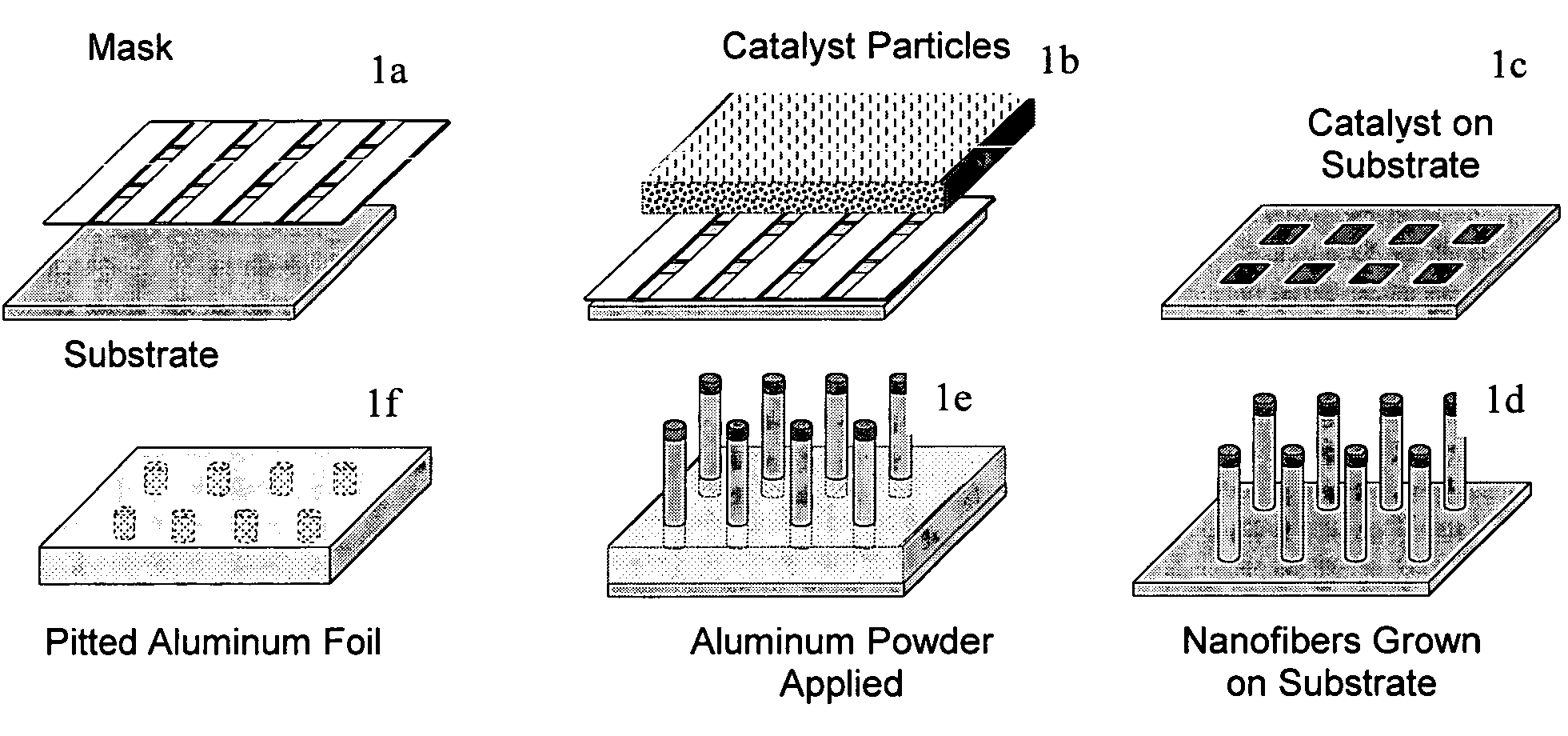
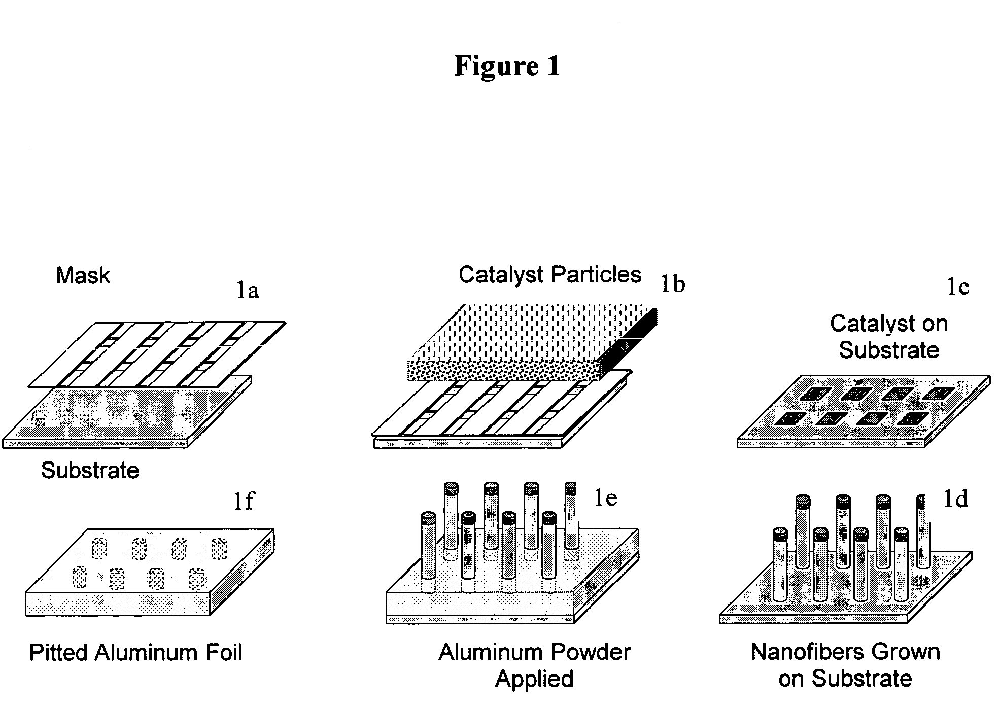
[0016]The method of the present invention incorporates the use of carbon nanofibers that are produced by the decomposition of a carbon-containing compound over metal catalyst particles at temperatures of about, 450° C. to about 800° C., preferably from about 500° C. to about 700° C., and more preferably from about 500° C. to about 600° C. The width of the carbon nanofibers is controlled by the size of the catalyst particle that in turn is manipulated by the substrate and treatment conditions employed. The present method generally involves: (i) placing a mask on top of a suitable substrate, which mask contains openings of a predetermined pattern and substantially uniform size; (ii) applying a layer of catalytic metal particles of a desired average particle size onto the mask / substrate; (iii) removing said mask from said substrate resulting in a predetermined pattern of catalytic metal sites on the substrate; (iv) growing carbon nanofibers from the catalytic metal particles on said su...


PUM

PropertyMeasurementUnit
Lengthaaaaaaaaaa
Sizeaaaaaaaaaa
Pore size distributionaaaaaaaaaa

Abstract

A method for making an aluminum foil anode for an aluminum electrolytic capacitor. This invention also relates to an aluminum anode foil for use in an electrolytic capacitor as well as an aluminum electrolytic capacitor having increased capacitance and substantially uniform pore size distribution.

Description

CROSS REFERENCE TO RELATED APPLICATIONS[0001]This application claims priority to Provisional Application Ser. No. 60 / 663,691 filed Mar. 21, 2005.FIELD OF THE INVENTION[0002]The present invention relates to a method for making an aluminum foil anode for an aluminum electrolytic capacitor. This invention also relates to an aluminum electrolytic capacitor having increased capacitance and substantially uniform pore size distribution.BACKGROUND OF THE INVENTION[0003]Aluminum electrolytic capacitors have several important commercial uses. For example, they are used: (a) for general purpose smoothing of signals (ripple current); (b) for energy storage in power supplies; (c) in pulse applications that release large bursts of energy in a short period of time (e.g., flash attachments for cameras, strobes and implantable defibrillators); and (d) specialty applications such as in starting motors for automobiles.[0004]Aluminum electrolytic capacitors are typically fabricated from two strips of a...

Claims


Application Information

Patent Timeline
IPC IPC(8): B22F3/11
CPCB22F3/1121H01G9/045H01G9/052
Inventor BAKER, R. TERRY K.RODRIGUEZ, NELLY M.
Owner CATALYTIC MATERIALS
Why Eureka
Try Eureka