Linear motor having progressive movement control

a technology of linear motors and control elements, applied in the direction of automatic controllers, dynamo-electric machines, instruments, etc., can solve the problems of increasing complexity of the mechanical system for sensing the position, increasing the difficulty of expanding an existing path, and requiring considerable time and technical effort to modify the system configuration. , to achieve the effect of excellent positioning accuracy and high rigidity

Inactive Publication Date: 2008-06-10
REXROTH INDRAMAT
View PDF10 Cites 28 Cited by
  • Summary
  • Abstract
  • Description
  • Claims
  • Application Information

AI Technical Summary

Benefits of technology

[0006]An example embodiment of the present invention may provide a linear motor such that, e.g., when using a multitude of secondary components, far-reaching modularity and flexibility may be provided, e.g., with respect to different applications or machine configurations, this being accomplished with a minimum of equipment and software. In order to be able to offer a modular system that is rapidly and easily adaptable to a wide variety of problem definitions, it may be provided that the number of secondary components is not restricted, so that the user may set up all types of conveyor systems having freely defined paths. One part of the movement controller is structurally provided on the secondary component such that the secondary component itself assumes a share of the computer-intensive movement control. This may significantly reduce the load on a possibly provided controller. The secondary component thus becomes a practically autonomously acting, intelligent unit, which, from an input of setpoints such as path inputs, and through the independent determination of actual values such as absolute position data, for instance, is able to initiate all actions for progressive movement on its own. In this manner, a local triggering of the required coils may be achieved in a simple manner, the setpoint then being used only for the coil controllers that are required to drive the secondary component in the desired direction or at the desired speed, etc. Such a movement control is practically a decentralized version or at least a partially decentralized version of the control, the movement control loop being split

Problems solved by technology

This may have the disadvantage that the mechanical system for sensing the position becomes increasingly more and more complex as the number of secondary components is increasing, reaching its limit with four to six secondary components (FIG. 10).
Moreover, it is more difficult to expand an existing path since the implementation of rail and secondary component depends on the number of secondary components.
Also, the already existing control has been configured for the specific application case, and a modification of the system configuration requires considerable time and technical effort.
The concept of using position sensing may also have the disadvantage that the generated signal will be falsified if even a single sensor breaks down, so that an eventual collision or a malfunction is thus virtually preprogrammed.
In addition, the wiring required for analyzing all sensor signals is considerable.
This may drastically increase the susceptibility to faults, in particular under adverse circumstances.
It may be disadvantageous that an external control would have to assume the entire process coordination and only straight movement paths can be realized.
However, the configuration of the secondary and primary components is similar to the design disclosed in U.S. Pat. No. 5,965,963 and hence may have the same disadvantages.
This may reduce the complexity of the overall system, so that more complicated application cases than conventional systems may be realized by distributed computer outputs and, in particular, distributed “intelligence” of the controller(s).
Unique means that the particular address is predefined only once for each secondary component and thus is unambiguous.
A relatively large part of the required logic circuit may be situated on the secondary component, so that the complexity of the circuits in the primary component may be very low.
In a similar manner, the signal-processing device also may generate a voltage setpoint, resulting in an higher demands on the bandwidth of the setpoint interface.
Especially with industrial machinery, a loss of production may cause considerably expense.
A plurality of secondary components may entail increased complexity of the associated control process.
Depending on the process, it may be limited solely by the process specifications, the geometry of the secondary components and the path design of the primary component.
A production line having one or a plurality of tool machines, for example, may require especially complex systems.

Method used


Image

  • Linear motor having progressive movement control
  • Linear motor having progressive movement control
  • Linear motor having progressive movement control

Examples


Embodiment Construction

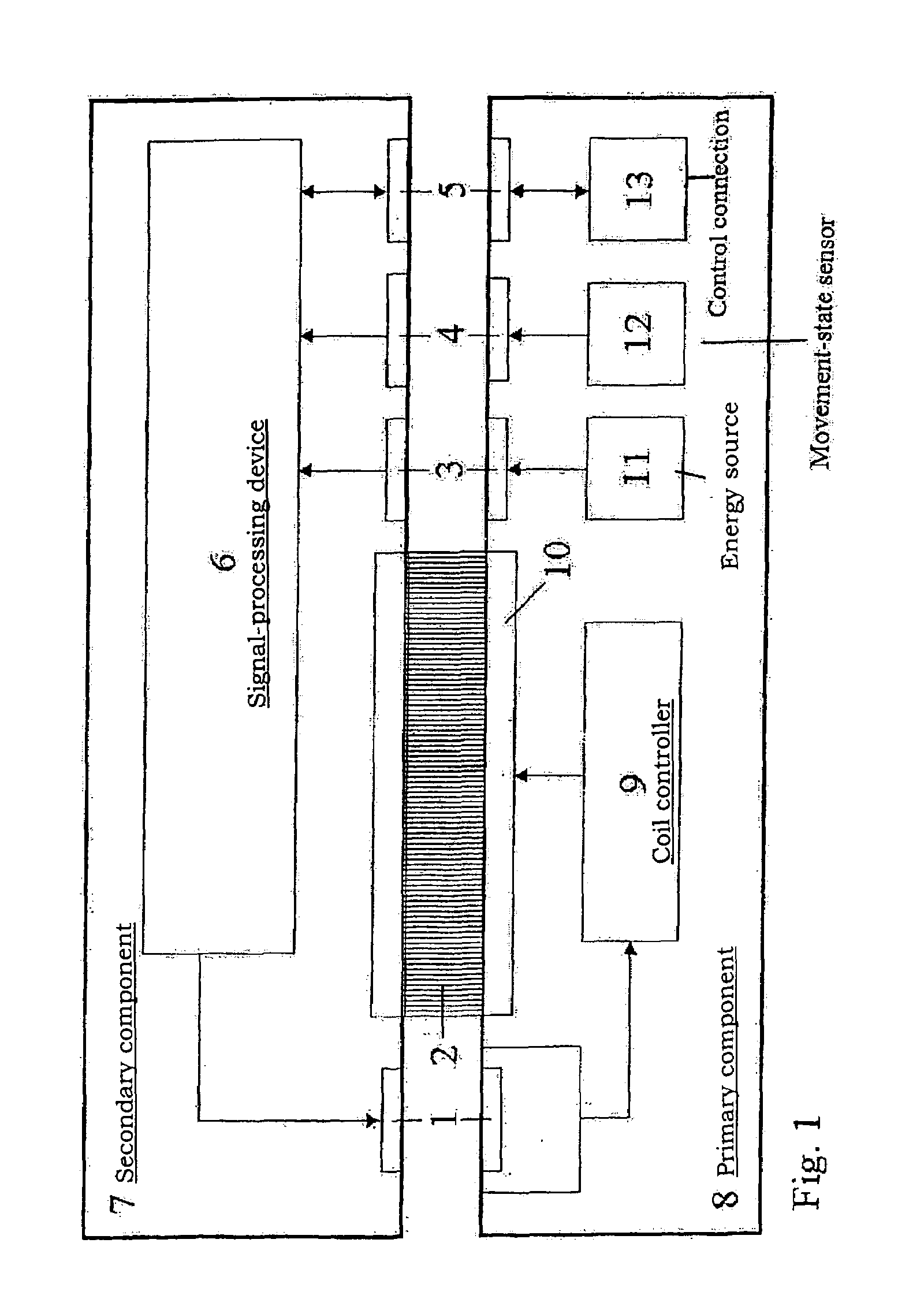
[0062]The linear motor illustrated in FIG. 1 includes a secondary component 7 and a primary component 8. The illustration is merely an example. For clarity, it illustrates only a single secondary component 7 in a sectional view. Primary component 8 forms a route, e.g., traveled by a plurality of secondary components 8 simultaneously.

[0063]Control connection 13 may ensure the connection to a controller, which is set up in a centralized or decentralized manner and implements the coordination of the movement process or of an entire industrial process. Control information is transmitted to corresponding and oppositely situated control interface 5 of the secondary component in a non-contacting fashion via control interface 5 on the primary component, which may be implemented as inductive, bidirectional interface in the specific example. Control interface 5 of the secondary component is connected to a signal-processing device 6, which analyzes the data received from the controller and in ...


PUM


Abstract

In a linear motor and its progressive motion or motion control, e.g., for modular transport devices with straight and curved route sections forming a route course, extensive modularity or flexibility of the linear motor may be guaranteed with little expenditure in terms of equipment and software, e.g., with regard to various applications or machine configurations, e.g., when a plurality of secondary parts are used. A secondary part may have at least one permanent magnet and a signal processing device with a progressive motion or motion controller, which generates at least one set value relevant to the coil control. A set value is fed as a magnitude for commutation using a set value interface of a coil control that is stationary relative to the primary part. Device(s) are also provided for rigidly positioning the secondary part, the device(s) guiding the secondary part along a predetermined stretch.

Description

FIELD OF THE INVENTION[0001]The present invention relates to a linear motor having progressive movement control, e.g., a linear motor having a plurality of secondary components (moved components), the linear motor, e.g., being used in processes of industrial automation.BACKGROUND INFORMATION[0002]U.S. Pat. No. 5,965,963 describes a linear motor made up of a secondary component and a primary component (stationary component), the secondary component implementing the triggering of the coils integrated in the path with the aid of position-sensing sensors such as Hall-effect sensors (FIG. 1B, FIG. 3), which are mounted along the path, and with the aid of a magnet situated on a secondary component. This may have the disadvantage that the mechanical system for sensing the position becomes increasingly more and more complex as the number of secondary components is increasing, reaching its limit with four to six secondary components (FIG. 10). Moreover, it is more difficult to expand an exis...

Claims


Application Information

Patent Timeline
Patent Type & Authority Patents(United States)
IPC IPC(8): H02K41/00H02P1/00H02K11/00H02K29/06H02K41/03
CPCH02K41/031H02K11/00H02K29/06
Inventor SCHEMM, EBERHARD
Owner REXROTH INDRAMAT
Why Eureka
Try Eureka