Peripheral ultrasonic sensing array system and method

a technology of ultrasonic sensing array and ultrasonic monitoring system, which is applied in the field of ultrasonic monitoring system, can solve the problems of destroying the evaluation and detection method and process in use today, destroying millions of dollars of vehicle accessories per year, and destroying millions of dollars of vehicle accessories. , to achieve the effect of improving the environment, improving the quality of the monitoring system, and more reliable and reliable results

Inactive Publication Date: 2008-06-17
GAYLE JAMES EDWARD MR
View PDF18 Cites 10 Cited by
  • Summary
  • Abstract
  • Description
  • Claims
  • Application Information

AI Technical Summary

Benefits of technology

[0007]The present invention was created to utilize recent technological advances to help progressive companies enhance their quality monitoring systems and achieve more reliable and dependable results in the quality of their products and their manufacturing processes. This diagnostic and detection system also improves the environment through the conservation of energy and resources and the creation of a more employee friendly atmosphere. Great cost efficiencies are also realized through reduced detection time and the increased ability to precisely locate leaks.

Problems solved by technology

Unfortunately, many of the evaluation and detection methods and processes in use today are destructive, time consuming, messy, unreliable, expensive, unsafe and fail to provide accurate results.
For example, water spray booths used for leak detection in the automotive industry ruin millions of dollars of vehicle accessories per year.
In addition, soap bubble testing for leaks in air, liquid, or gaseous systems are inaccurate and create messes that can contribute to unsafe, slip and fall type potential hazards.
However, the hand held ultrasonic sensing devices typically used are time consuming to use and produce inconsistent results that are difficult to compare over time.

Method used


Image

  • Peripheral ultrasonic sensing array system and method
  • Peripheral ultrasonic sensing array system and method
  • Peripheral ultrasonic sensing array system and method

Examples


Embodiment Construction

[0012]The knowledge and experience of Jimmy Gayle in the area of ultrasonic detection was put to use in the invention of a new ultrasonic sensing product which solves the above described problems by providing a cost effective, easy to use, ultrasonic detection system that is readily adaptable to a modern manufacturing environment. More particularly, it was discovered that by utilizing amplitude sensitive ultrasonic sensing technology and selecting the proper frequency level and modulation method for sending and receiving the ultrasonic signals, an extremely reliable and accurate ultrasonic leak detection device could be created.

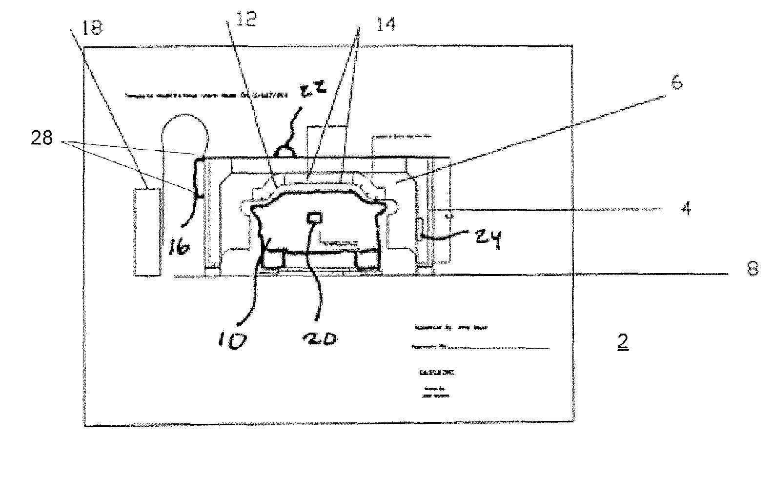
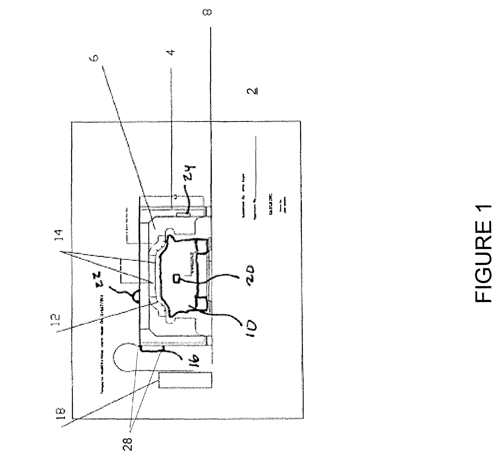
[0013]Referring now to FIG. 1, a diagram of an embodiment of the present invention is shown. The system 2 consists of a substantially rectangular frame 4 having an insertable, customized sensing silhouette 6 or template 6. The frame 4 is positioned over a section of a manufacturing line 8 so that the products being manufactured on the line 8 pass beneath the ...


PUM

PropertyMeasurementUnit
depthaaaaaaaaaa
frequencyaaaaaaaaaa
transmitted frequencyaaaaaaaaaa

Abstract

An improved system and method for detecting leaks in substantially enclosed objects such as automobiles, airplanes, tanks, etc. uses an ultrasonic transmitter and an array of ultrasonic sensors positioned around the inner periphery of a cut out silhouette that corresponds to an outline of the objects under test. The silhouette is mounted in a frame that is designed to minimize ultrasonic reflections and preserve any amplitude information received by the ultrasonic sensors. As the objects are passed through the frame, ultrasonic amplitude readings obtained from the sensors are processed to determine if they are representative of a defective or leaking object. The position of the leak is determined by examining the amplitude of the individual sensor readings. The system is particularly well adapted for use in detecting defects in automobiles on an assembly line without interrupting the assembly process or damaging the car.

Description

CROSS-REFERENCES TO RELATED APPLICATIONS[0001]The present application is a Continuation-In-Part application which claims the benefit of and priority from U.S. patent application Ser. No. 10 / 320,671 filed Dec. 17, 2002 now abandoned, entitled “Ultraphonics Array System” which is hereby incorporated by reference, and which claimed the benefit of provisional application 60 / 341,553 filed Dec. 17, 2001 and entitled “Ultraphonics Array System.”STATEMENT REGARDING FEDERALLY SPONSORED RESEARCH OR DEVELOPMENT[0002]Not ApplicableREFERENCE TO SEQUENCE LISTING OR COMPUTER PROGRAM LISTING APPENDIX[0003]Not ApplicableFIELD OF THE INVENTION[0004]The present invention is directed toward the field of ultrasonic monitoring systems. More particularly, the present invention is directed toward an ultrasonic monitoring system for detecting defects or leaks in manufactured items.BACKGROUND OF THE INVENTION[0005]The present invention is the result of extensive, long-term research by the present inventor in...

Claims


Application Information

Patent Timeline
Patent Type & Authority Patents(United States)
IPC IPC(8): G01N29/02G01N29/11G01N29/34G01N29/44
CPCG01N29/348G01N29/4445G01N29/11G01N2291/106G01N2291/2695
Inventor GAYLE, JAMES EDWARD
Owner GAYLE JAMES EDWARD MR
Why Eureka
Try Eureka