DQPSK receiver phase control

a receiver and phase control technology, applied in electromagnetic transmission, multiplex communication, electrical equipment, etc., can solve the problems of low control signal sensitivity, unbalanced mzi of each mzi, and inability of the receiver to efficiently demodulate the transmitted data

Active Publication Date: 2008-06-17
CIENA
View PDF8 Cites 46 Cited by
  • Summary
  • Abstract
  • Description
  • Claims
  • Application Information

AI Technical Summary

Benefits of technology

[0013]Advantageously, the receiver can provide a more effective and reliable control because the difference between the maxima and minima of the control signal is greater than in conventional approaches and because the rate of change of the control signal at the tuning point is greater than in conventional approaches. This can enable better phase control and so fewer bit errors or larger margins such as power margins for the transmission system.
[0017]In one embodiment, the receiver comprises a squaring circuit to square the signal from the device. In a further embodiment, the receiver comprises circuitry for filtering a tone from the output of the square law detector. This can help to isolate the wanted tone from other unwanted artifacts of the signal processing, to improve the control.
[0018]In one embodiment, the phase controller is arranged to tune the phase response of the optical component at a substantially lower rate than a data rate of the received signal. This helps to remove data dependence.
[0019]In one embodiment, the receiver comprises a balanced detector for converting the output of the optical component to an electrical signal. Such balanced detectors can be more efficient in using the available light, especially from the output of interferometers or other optical components having complementary optical outputs.

Problems solved by technology

A drawback to this system is the requirement that the receiver must have a reference oscillator matched in phase to the transmitter oscillator; that is, the decoding is done by coherent detection.
If the frequencies of the two oscillators are not matched, the receiver cannot efficiently demodulate the transmitted data.
Each MZI is unbalanced in that each has a time delay of approximately one symbol period (50 ps for a 20 Gsymbol / s line rate) of the data modulation rate, in one arm relative to that of the other arm, by making the physical length of one arm longer than that of the other arm.
However, the sensitivity of the control signal is low because the difference between maxima and minima is small and because the rate of change of the control signal is low or zero at the optimum operating point.
Thus, the control signal is easily swamped by spurious noise and other effects.
This gives a weak drive to the control loop so that the operating point is prone to error.

Method used


Image

  • DQPSK receiver phase control
  • DQPSK receiver phase control
  • DQPSK receiver phase control

Examples


Embodiment Construction

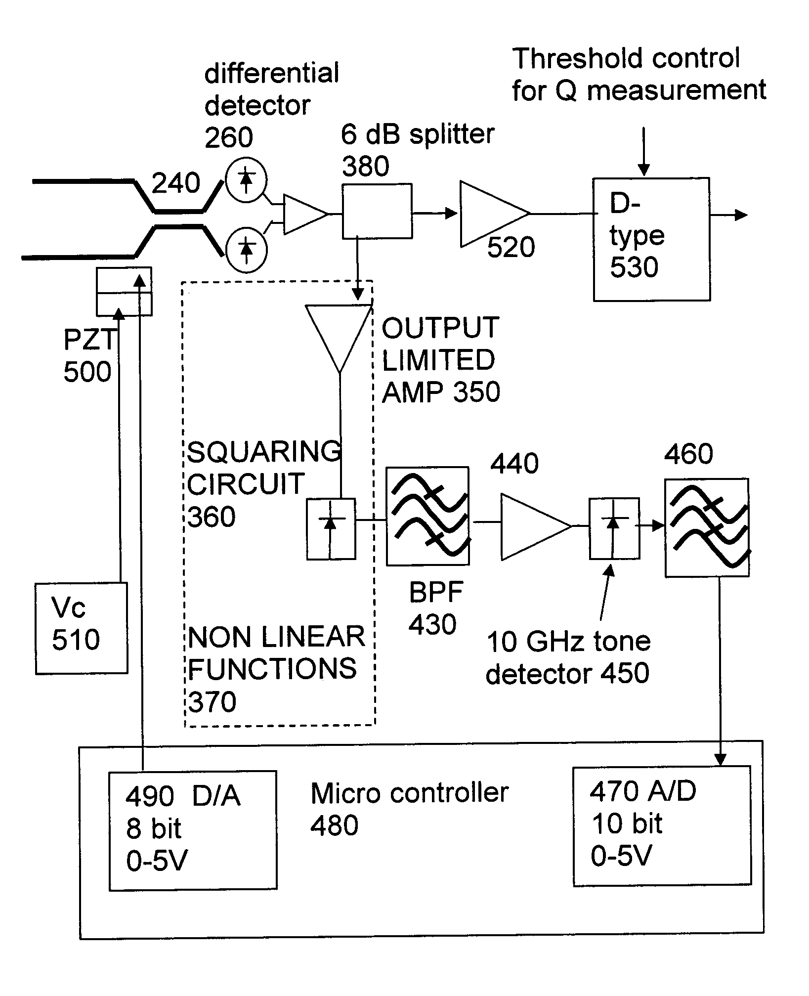
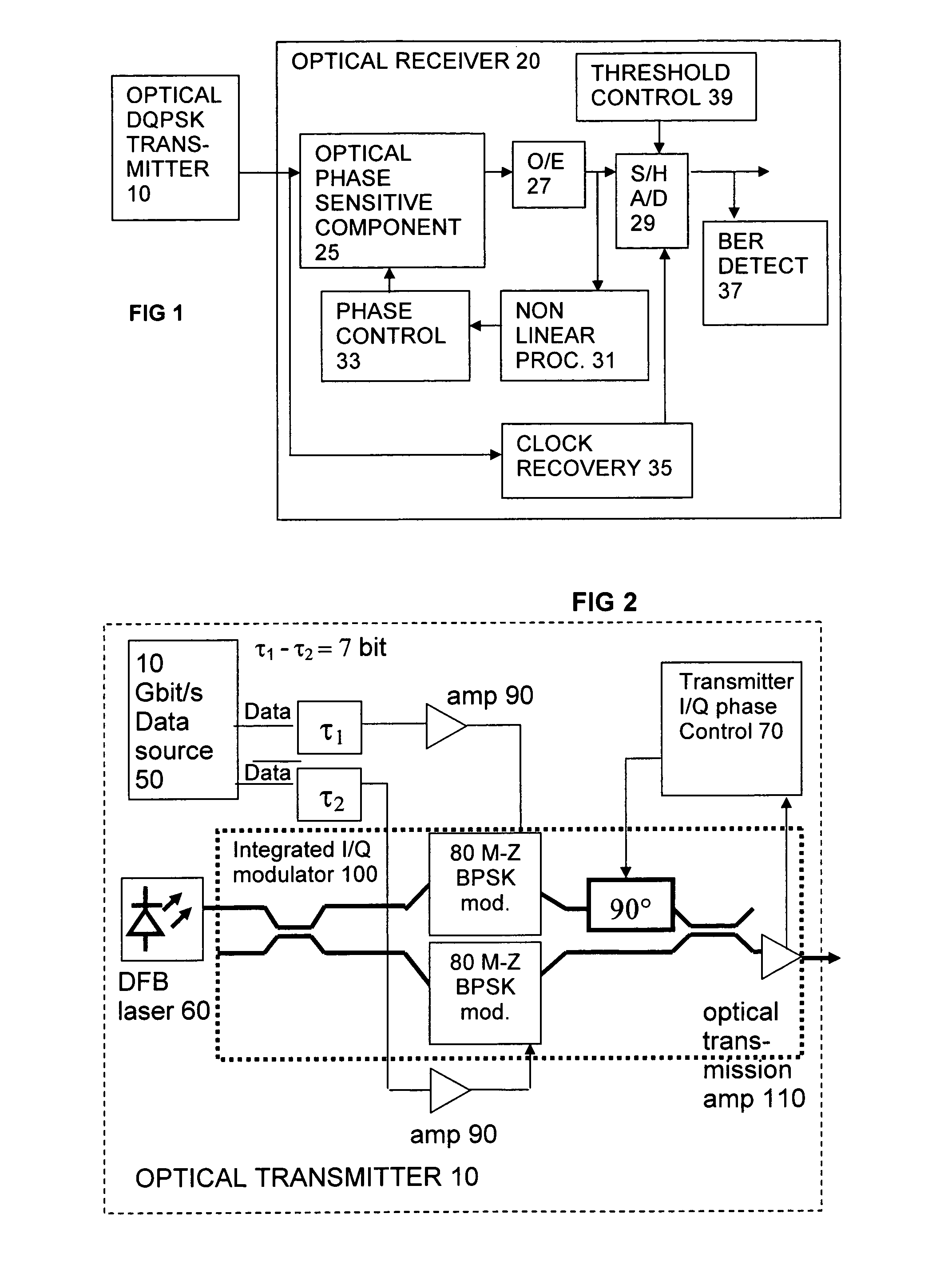
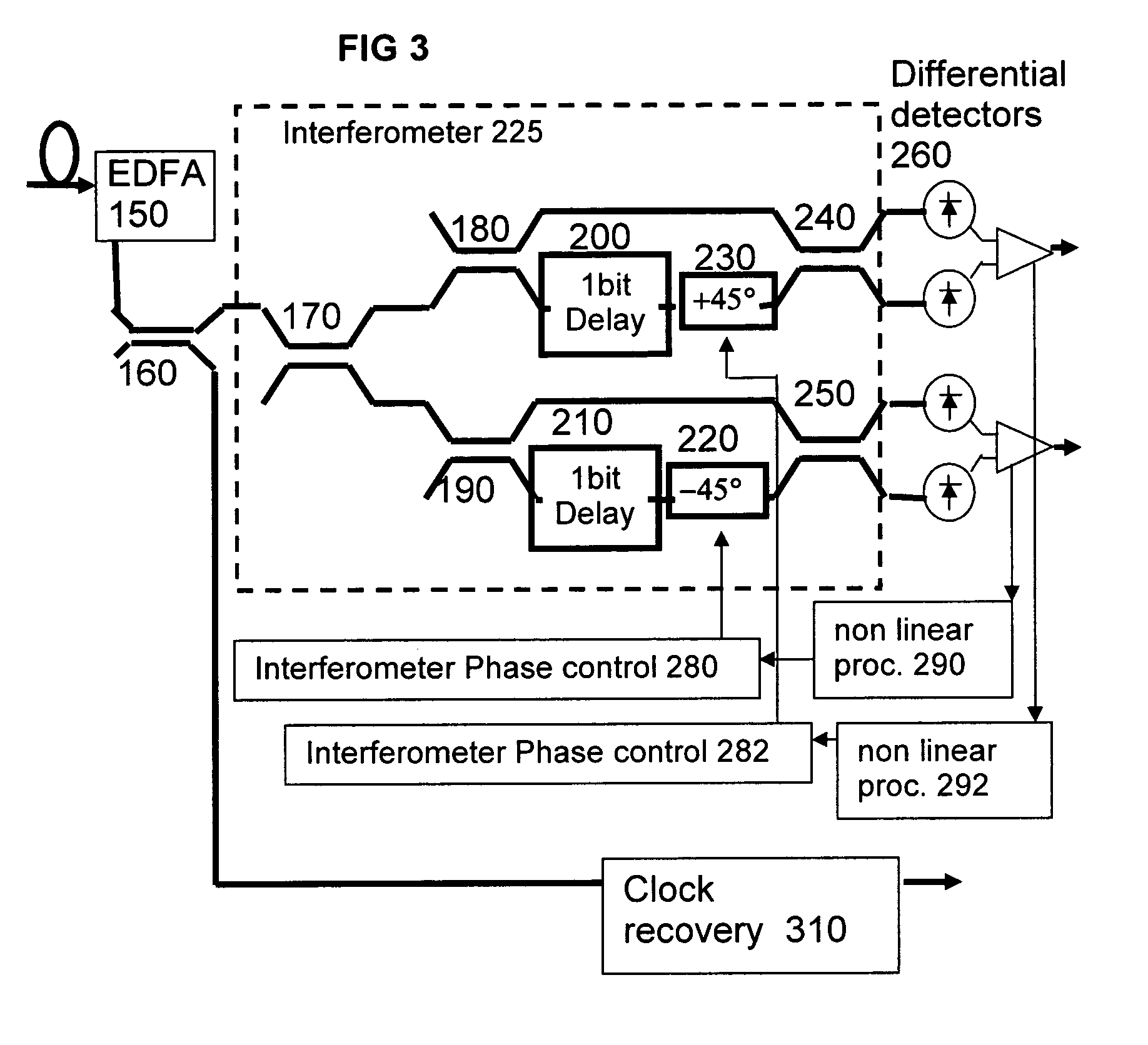
[0031]The embodiments relate to an optical DQPSK receiver which is set to the optimum operating point in terms of the differential phase delay between the two paths through the interferometer on the basis of maximizing a cost function derived from the received signal. The cost function is generated by amplifying the output from a balanced receiver on the output of an interferometer. The gain is sufficient that the amplifier is operating in its non-linear region, i.e. the signal is in compression. The amplifier is followed by a square law detector which in combination with the non-linear characteristic of the amplifier produces a tone at the baud rate of the incoming signal. When the power in the tone is at a maximum, the operating point of the interferometer is correct for the reception of DQPSK (i.e. + or −pi / 4).

[0032]DQPSK modulation is proposed in combination with the modulation of two polarization states is one way to increase the capacity of Next Generation Modem systems from 1...


PUM


Abstract

An optical receiver for receiving an optical differential phase shift keyed signal has an optical component sensitive to the optical phase of the signal, such as an interferometer, a device arranged to generate a control signal by non linear limiting of an output of the optical component, such as an RF amplifier arranged to operate in a region near saturation point, and a phase controller for tuning a phase response of the optical component to the received signal according to the control signal.

Description

FIELD OF THE INVENTION[0001]This invention relates to receivers for optical differential phase shift keyed transmission systems, to methods of receiving, and to methods of offering a transmission service over such apparatus.BACKGROUND TO THE INVENTION[0002]It is known to provide a receiver for an optical transmission system which converts an optical signal to electrical form, then samples the signal to detect digital ones and zeroes for example. Such sampling requires an amplitude threshold to be set, and a clock phase to be set. This usually involves providing a clock recovery circuit for determining and continually adjusting the timing of the sampling. Such clock recovery circuits typically use a phase locked loop controlled in association with the threshold level to maximize an “eye opening” of the received waveform.[0003]There are various ways of modulating the data at the transmitter and demodulating at the receiver, most based on altering phase or amplitude. Quadriphase or qua...

Claims


Application Information

Patent Timeline
Patent Type & Authority Patents(United States)
IPC IPC(8): H04B10/06
CPCH04B10/505H04B10/5053H04B10/50577H04B10/677H04B10/6911H04B10/695
Inventor RICKARD, ROBINKEE, HUALROBINSON, ALAN
Owner CIENA
Why Eureka
Try Eureka