
Power augmentation of combustion turbines by injection of cold air upstream of compressor

a technology of combustion turbines and compressors, which is applied in the direction of hot gas positive displacement engine plants, machines/engines, jet propulsion plants, etc., can solve the problems of significant power degradation of combustion turbine power generating systems, reduced inlet airflow mass, and limited type of inlet air cooling

Inactive Publication Date: 2008-06-24
DRESSER RAND CO
View PDF10 Cites 51 Cited by
  • Summary
  • Abstract
  • Description
  • Claims
  • Application Information

AI Technical Summary

Benefits of technology

[0006]In accordance with another aspect of the invention, a method of reducing a temperate of inlet air to a combustion turbine assembly is provided. The combustion turbine assembly includes a main compressor constructed and arranged to receive ambient inlet air, a main expansion turbine operatively associated with the main compressor, a combustor constructed and arranged to receive compressed air from the main compressor and to feed the main expansion turbine, and an electric gene...

Problems solved by technology

It is well known that combustion turbine power generating systems have significant power degradation associated with increased ambient temperature or high elevations.
This loss of power is primarily associated with the reduced inlet airflow mass of the combustion turbine power generating systems, caused by the reduced inlet ambient air density.
However, this type of inlet air cooling is limited in areas that don't have a sufficient supply of water available.
However, high capital cost and high operating and maintenance costs are associated with these chillers.

Method used


Image

  • Power augmentation of combustion turbines by injection of cold air upstream of compressor
  • Power augmentation of combustion turbines by injection of cold air upstream of compressor
  • Power augmentation of combustion turbines by injection of cold air upstream of compressor

Examples


Embodiment Construction

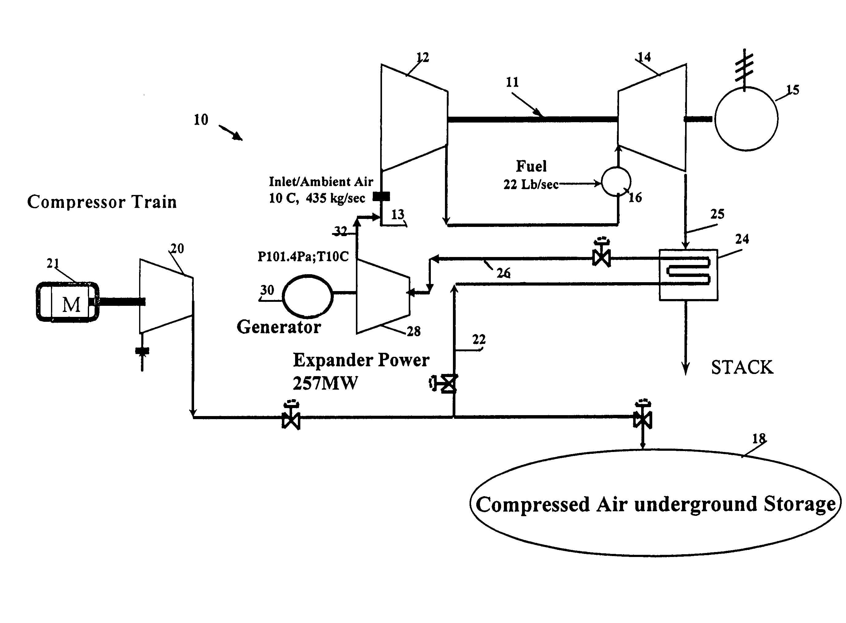
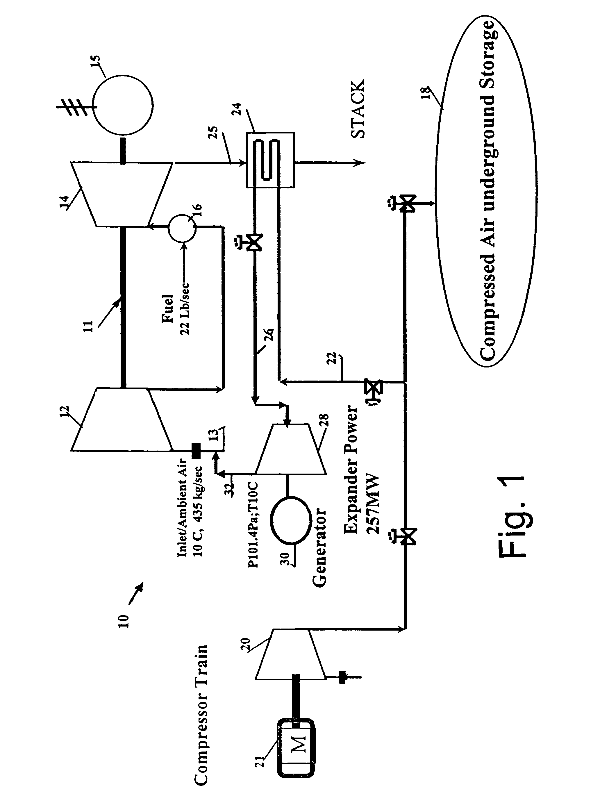
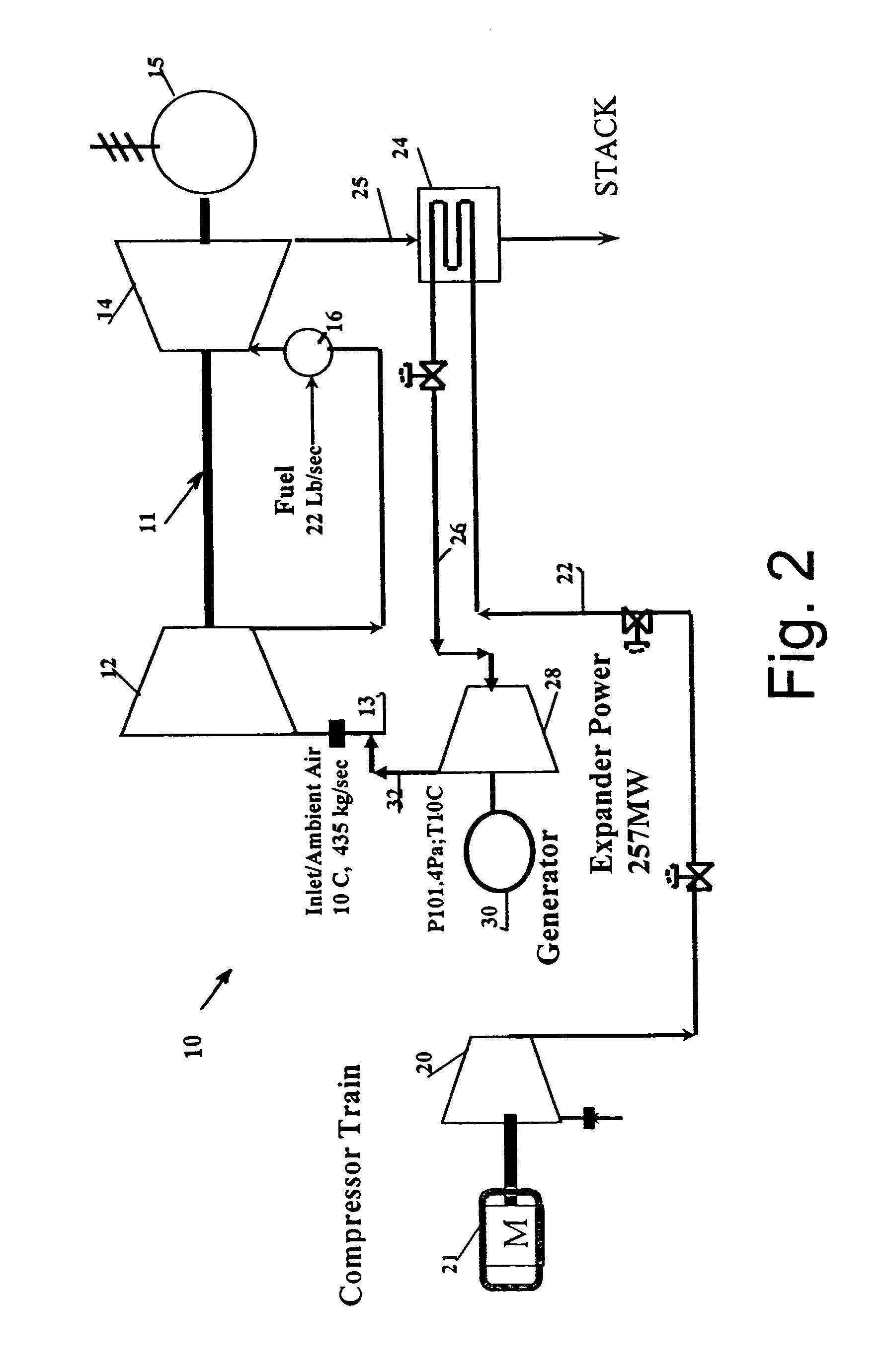
[0011]With reference to FIG. 1, a combustion turbine power generation system with power augmentation, generally indicated as 10, is shown in accordance with an embodiment of the present invention. The system 10 includes a conventional combustion turbine assembly, generally indicated at 11, having a main compressor 12 receiving, at inlet 13, a source of inlet air at ambient temperature and feeding a combustor 16 with the compressed air; a main expansion turbine 14 operatively associated with the main compressor 12, with the combustor 16 feeding the main expansion turbine 14, and an electric generator 15 for generating electric power.

[0012]In accordance with an embodiment, compressed air storage 18 is provided. The storage 18 is preferably an underground storage structure that stores air that is compressed by at least one auxiliary compressor 20. In the embodiment, the auxiliary compressor 20 is driven by a motor 21, but can be driven by an expander or any other source. The auxiliary ...


PUM


Abstract

A combustion turbine power generation system 10 includes a combustion turbine assembly 11 including a main compressor 12 constructed and arranged to receive ambient inlet air, a main expansion turbine 14 operatively associated with the main compressor, a combustor 16 constructed and arranged to receive compressed air from the main compressor and to feed the main expansion turbine, and an electric generator 15 associated with the main expansion turbine for generating electric power. Pressure reducing structure 28 is constructed and arranged to reduce pressure of compressed air from a source of compressed air to atmospheric pressure and thus to reduce a temperature of the compressed air from the source of compressed air to a temperature below ambient temperature when exhausted from the pressure reducing structure. Structure 32 is associated with the pressure reducing structure to permit mixing of the air exhausted from the pressure reducing structure and the ambient inlet air to reduce a temperature of inlet air to the main compressor and thus increase the combustion turbine assembly power.

Description

FIELD OF THE INVENTION[0001]This invention relates to combustion turbine power systems and, more particularly, to augmenting power of the system by reducing air temperature at an inlet of the main compressor of the system.BACKGROUND OF THE INVENTION[0002]It is well known that combustion turbine power generating systems have significant power degradation associated with increased ambient temperature or high elevations. This loss of power is primarily associated with the reduced inlet airflow mass of the combustion turbine power generating systems, caused by the reduced inlet ambient air density.[0003]There are a number of technologies that pre-condition inlet air to recover power lost by combustion turbines due to high ambient temperatures / high elevation. For example, evaporative coolers, inlet fogging and “wet compression” technologies provide power augmentation by a combination of inlet air humidification and cooling with associated increased mass flow through the combustion turbin...

Claims


Application Information

Patent Timeline
IPC IPC(8): F02C7/00
CPCF02C6/16Y02E60/15Y02E20/16Y02E60/16
Inventor NAKHAMKIN, MICHAEL
Owner DRESSER RAND CO
Features
  • Generate Ideas
  • Intellectual Property
  • Life Sciences
  • Materials
  • Tech Scout
  • Unparalleled Data Quality
  • Higher Quality Content
  • 60% Fewer Hallucinations
Learn More