
Electric power control system for a hybrid vehicle

a power control system and hybrid technology, applied in the direction of electric generator control, engine starters, electric devices, etc., can solve the problems of large voltage swing, unsatisfactory voltage swing, and large voltage swing during dynamic engine-stop-start functions and engine stops (at idle), so as to enhance system efficiency and improve pleasurability and performance.

Inactive Publication Date: 2008-06-24
GM GLOBAL TECH OPERATIONS LLC
View PDF16 Cites 29 Cited by
  • Summary
  • Abstract
  • Description
  • Claims
  • Application Information

AI Technical Summary

Benefits of technology

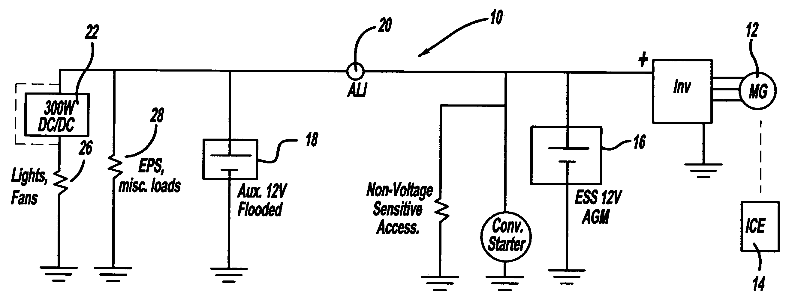
[0007]The present invention includes a method and apparatus to improve the pleasability and performance for a single-voltage hybrid system. The system may include a vehicle having both parallel and series hybrid drive systems incorporating an ICE, MoGen and a battery pack. The hybrid drive system of the present invention will utilize the ICE and MoGen to propel or motor the vehicle during the vehicle conditions which are most efficient for the ICE or MoGen operation. During normal operation of the vehicle when the ICE is running, the MoGen may act as an electrical generator to supply electrical power to the vehicle's electrical infrastructure (fans, radios, instrumentation, control, etc.) as well as recharging the battery pack.
[0008]In the preferred embodiment of the present invention, the battery pack is comprised of two single-voltage batteries. The second battery is connected in parallel with an accessory load isolator (ALI) to actively decouple the hybrid-related power flow from the voltage-sensitive accessory power flow. A DC / DC converter may also be used to bypass the power during the vehicle cruising / charging conditions to enhance system efficiency. The output voltage of the DC / DC converter can be ramped to converge with the charging bus voltage, before the bypass is executed.

Problems solved by technology

If a hybrid system is implemented into a conventional 12V electrical system, the voltage swings during dynamic Engine-Stop-Start (ESS) functions and engine stops (at idle) could be unsatisfactory.
For example, when performing ESS functions, the large power draw results in large voltage swings.
These voltage dips and surges result in customer distractions such as undulating headlights / dashlights and blower speed.
These voltage swings can also present a performance issue if the battery or battery pack (already strained from ESS action) is needed to support accessories such as Electric Power Steering (EPS).

Method used


Image

  • Electric power control system for a hybrid vehicle
  • Electric power control system for a hybrid vehicle

Examples


Embodiment Construction

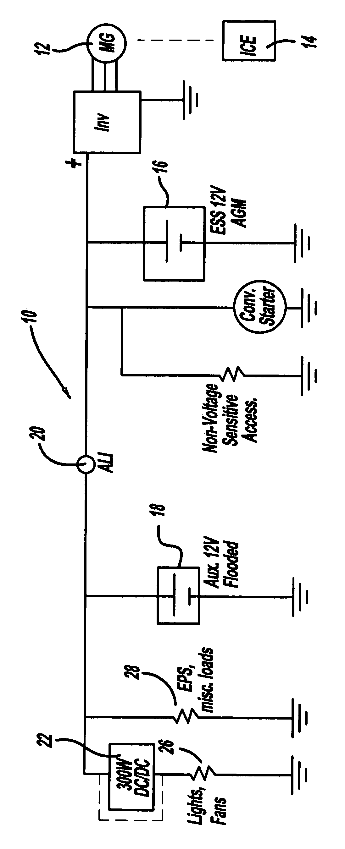
[0010]The FIGURE is a diagrammatic drawing of a hybrid vehicle system 10 of the present invention. A motor generator (MoGen) 12 is dynamically coupled to an internal combustion engine (ICE) 14 and functions as either a motor to propel the vehicle or a generator to charge a battery pack, depending on the operating state of the vehicle (i.e. braking, stopped, or operating at a constant speed on a highway). The MoGen 12 is preferably an AC induction machine but may comprise any known electrical motor / generator technology, including, but not limited to, DC machines, internal permanent magnet motors, brushless motors, synchronous machines, and switched reluctance machines.

[0011]In the preferred embodiment, the battery pack is comprised of two 12 volt batteries. The battery types used in the present invention include, but are not limited to, lead-acid, nickel metal hydride, lithium ion, lithium polymer, or any other battery technology that may be used in a vehicle. In the preferred embodi...


PUM


Abstract

A vehicle powertrain control system including an electric motor drive system, a first battery coupled to the electric motor drive system, an electronically controlled switched coupled to the first battery, a second battery coupled to the electronically controlled switch, and where the electronically controlled switch applies power from the second battery to supplement the first battery.

Description

TECHNICAL FIELD[0001]The present invention relates to the power control system for a hybrid powertrain. More specifically the present invention relates to a single-voltage electric power control system for a hybrid powertrain.BACKGROUND OF THE INVENTION[0002]The increasing demand to improve fuel economy, eliminate emissions, and reduce noise levels has driven the automotive market to develop a variety of propulsion mechanisms. As an alternative to the traditional internal combustion engine (ICE) powertrain the industry has developed a hybrid electric system powered by an electric traction motor(s) and an internal combustion engine. During varying driving conditions, hybrid electric vehicles (HEVs) will alternate between the separate power sources, depending on the most efficient manner of operation of each source.[0003]A HEV may contain either a parallel drivetrain configuration or a series drivetrain configuration. Either of the configurations allows the ICE to perform relatively m...

Claims


Application Information

Patent Timeline
Patent Type & Authority Patents(United States)
IPC IPC(8): B60K1/00B60L50/15B60KB60L1/00
CPCB60L1/00B60L2220/18
Inventor TAMAI, GOROREYNOLDS, MICHAEL G.
Owner GM GLOBAL TECH OPERATIONS LLC
Learn More