Composite cryogenic propellant tank including an integrated floating compliant liner

a cryogenic propellant and liner technology, applied in the field of storage tanks, can solve the problems of failure of composite tanks using lox, failure of cryogenic propellants such as lox in high-pressure, etc., and achieve the effect of facilitating particle redistribution and low coefficien

Inactive Publication Date: 2008-06-24
US SEC THE AIR FORCE THE
View PDF3 Cites 13 Cited by
  • Summary
  • Abstract
  • Description
  • Claims
  • Application Information

AI Technical Summary

Benefits of technology

[0010]It is yet another feature of the present invention to provide an integrated floating complaint liner design for tanks wherein each micro-particle operates to form a collective hermetical seal under pressure between the tank wall and floating compliant liner and collectively enables the tank system to survive high numbers of deep the

Problems solved by technology

There has been no successful demonstration of cryogenic propellants such as LOX in a high-pressure composite tank.
Most composite tank failures using LOX can be attributed to

Method used


Image

  • Composite cryogenic propellant tank including an integrated floating compliant liner
  • Composite cryogenic propellant tank including an integrated floating compliant liner
  • Composite cryogenic propellant tank including an integrated floating compliant liner

Examples


Embodiment Construction

[0020]As previously mentioned, experiments have shown that carbon fiber / epoxy materials microcrack when used with cryogenic propellants due to large differences in the coefficient of thermal expansion between the carbon fiber and epoxy matrix. Acknowledging this limitation, the present inventor developed an integrated floating compliant liner design for tanks.

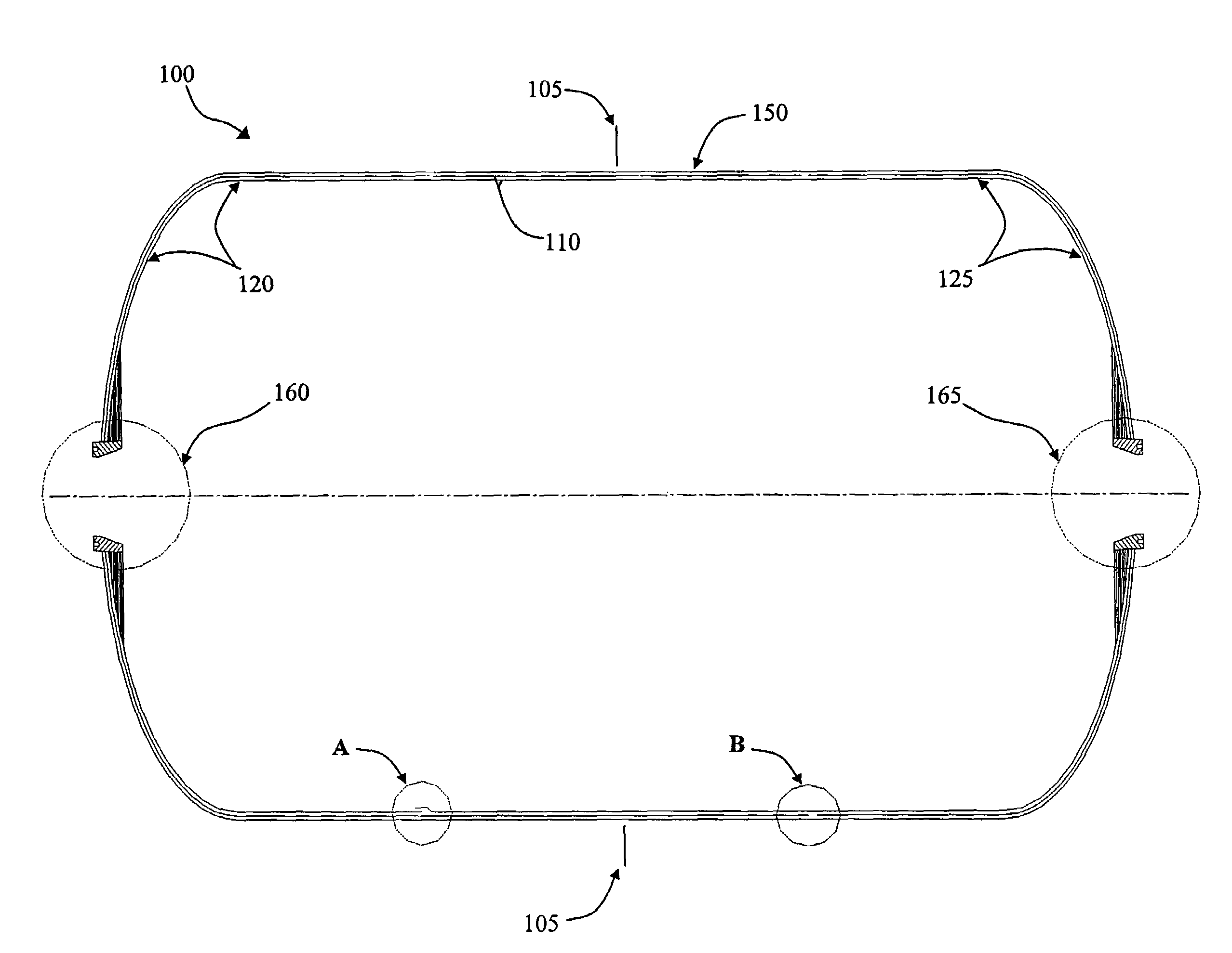
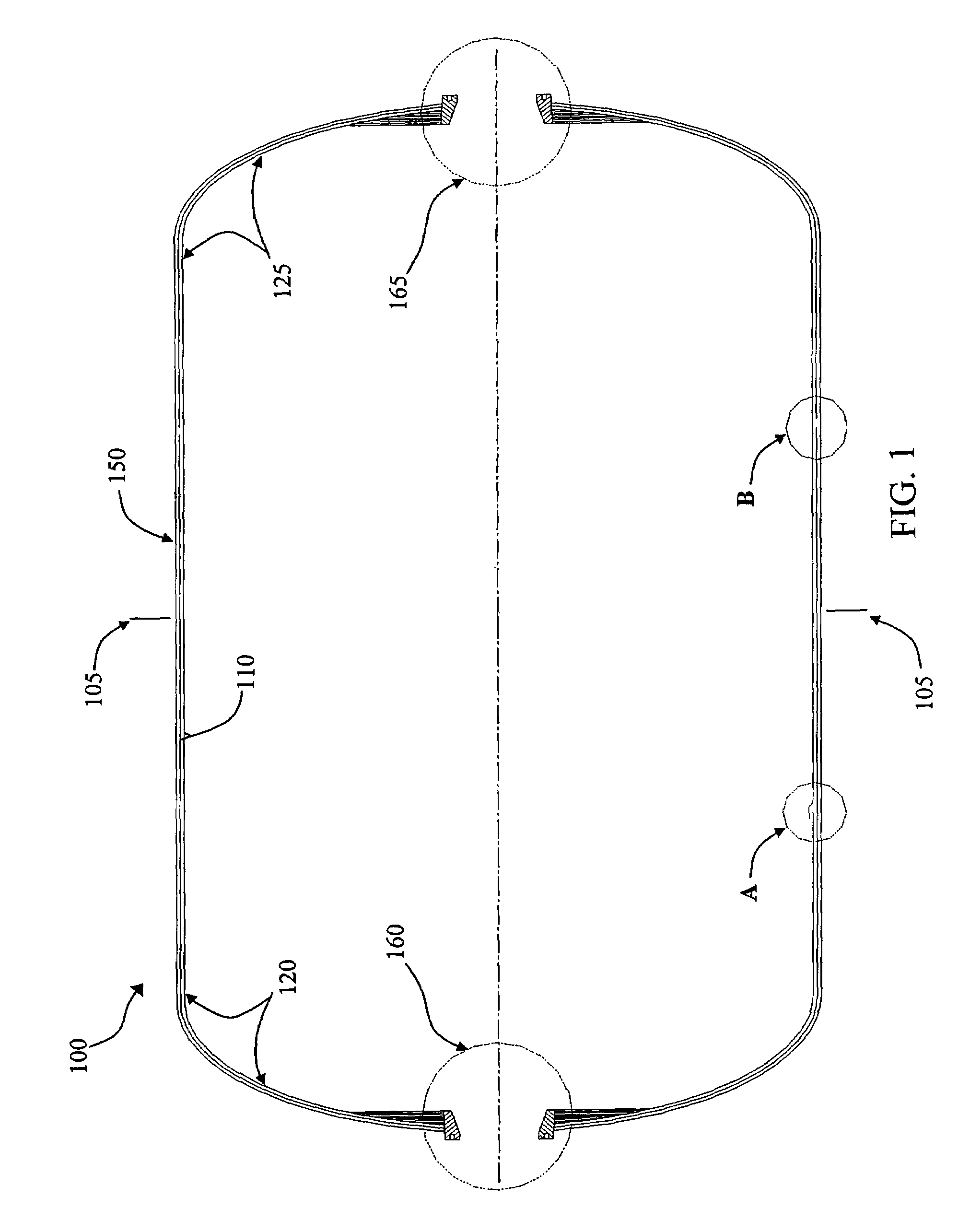
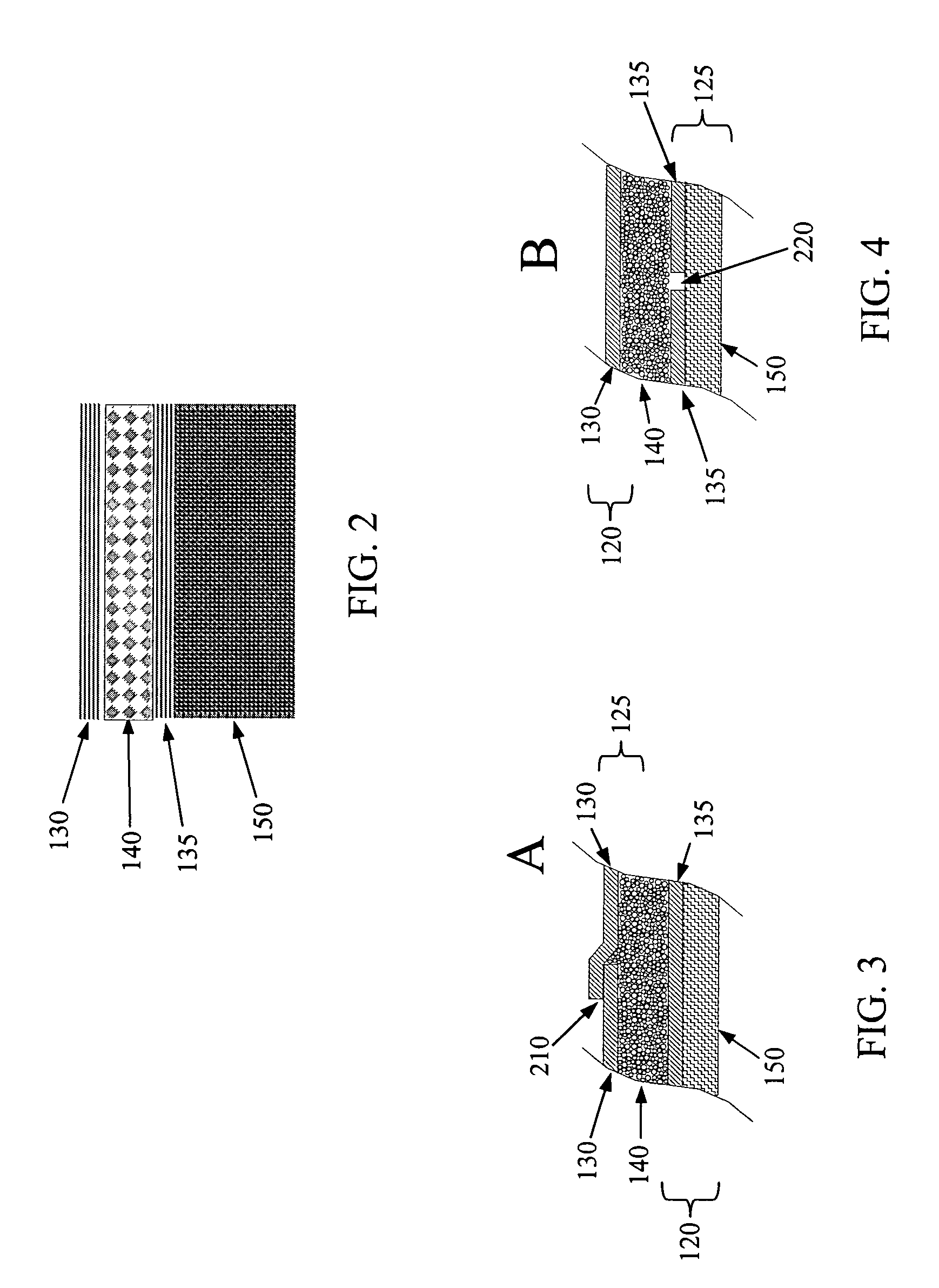
[0021]Referring to FIG. 1, it is a feature of the present invention to provide a tank 100 that includes an inner floating liner structure 110. The inner floating liner structure 110 can include interlocking shells 120 / 125 comprised of carbon fiber / epoxy and formed in a cylindrical, end dome geometry. The interlocking shells 120 / 125 can be sectioned to provide surface 130 and inner 135 layers that overlap and extend beyond the tank's 100 midpoints 105, resulting in interconnections as shown at locations A and B. A pair of separately fabricated polar bosses 160 / 165 seal against the inner of the two interlocking floating liner she...


PUM

PropertyMeasurementUnit
Diameteraaaaaaaaaa
Sizeaaaaaaaaaa
Polarityaaaaaaaaaa

Abstract

A tank suitable for containing cryogenic propellant includes an inner liner structure comprised of two layers forming a gap. An intermediary layer comprised of micro-particles is disposed in the gap formed between the two layers of the inner liner structure. A structural overwrap layer covers the inner liner structure in a manner that enables the inner liner structure to float within the structural overwrap layer. The inner floating liner structure can be formed by two thin interlocking (outer and inner) shell s formed in a cylindrical, end dome geometry. The inner and outer shells are both sectioned beyond the tank midpoints. The micro-particles can be comprised of PTFE. An outer structural overwrap comprised of graphite/epoxy covers the double shell liner. A pair of separately fabricated polar bosses seal against the inner of the two interlocking floating liner shells are then each bonded to the tank, fittings, and piping.

Description

STATEMENT OF GOVERNMENT INTEREST[0001]The conditions under which this invention was made are such as to entitle the Government of the United States under paragraph 1(a) of Executive Order 10096, as represented by the Secretary of the Air Force, to the entire right, title and interest therein, including foreign rights.FIELD OF THE INVENTION[0002]The present invention is generally related to storage tanks. More particularly, the present invention is related to light-weight, self-sealing cryogenic propellant storage tanks.BACKGROUND OF THE INVENTION[0003]Historically, propellant tanks for liquid rockets have been manufactured using metal. Recently, composite tanks made using, for example, graphite or epoxy have been used for storable propellants such as kerosene and as high pressure tanks in order to reduce their structural weight, and thus the overall weight of dependent systems.[0004]Liquid oxygen (LOX), a cryogenic propellant, is one of the most efficient oxidizers from a mass and p...

Claims


Application Information

Patent Timeline
IPC IPC(8): F17C1/06
CPCF17C1/16F17C2201/0104F17C2201/054F17C2203/0604F17C2203/0621F17C2203/0624F17C2203/0663F17C2203/0673F17C2209/2163F17C2221/011F17C2223/0161F17C2223/033F17C2270/0197F17C2205/0305
Inventor HAMPSTEN, KENNETH R.
Owner US SEC THE AIR FORCE THE
Why Eureka
Try Eureka