Switching power source device

a power source device and switching frequency technology, applied in lock applications, process and machine control, instruments, etc., can solve the problems of power source breakdown, output voltage to rise undetectedly, and increase switching loss and generated heat, so as to reduce or minimize all harmful effects, control, and reduce the effect of reducing or minimizing all harmful effects

Inactive Publication Date: 2008-06-24
SANKEN ELECTRIC CO LTD
View PDF13 Cites 32 Cited by
  • Summary
  • Abstract
  • Description
  • Claims
  • Application Information

AI Technical Summary

Benefits of technology

[0012]During the light load period, second comparator (52) compares error output from error amplifier (26) with the numerical value from sweep circuit (57) to produce the output from second comparator (52) when the numerical value exceeds a level of the output from error amplifier (26) so that the output from second comparator (52) serves to stop the on action of the switching element (4) to restrict an undesirable rise in output voltage. Consequently, the device can control, reduce or minimize all harmful effects such as excessive voltage applied on smoothing capacitor (16) and malfunction resulted therefrom, increase in switching loss and generated heat associated with rise in switching frequency of the switching element (4), declination in conversion efficiency of electric power, and evolution of heat from drive resistor (38).

Problems solved by technology

In view of a fact that prior art switching power source device shown in FIG. 8 increases switching frequency of operating MOS-FET 4 during the light load period, elevated switching frequency may produce a disadvantageous delay in response of control circuit 10 or MOS-FET 4.
If this is the case, control circuit 10 cannot shorten the drive signal for MOS-FET 4 to an optimal on-pulse width, thereby causing output voltage to undesirably rise and excessive voltage to appear on smoothing capacitor 16, expanding a risk of causing breakdown of the power source.
Also, it has other drawbacks that increase in switching frequency during the light load period leads step-up in switching loss and amount of generated heat and big reduction in conversion efficiency of electric power.
Moreover, drive resistor 38 connected between NOR gate 33 and gate terminal of MOS-FET 4 generates increased amount of heat, and therefore, unfavorably requires its large capacity in electric power.

Method used


Image

  • Switching power source device
  • Switching power source device
  • Switching power source device

Examples


first embodiment

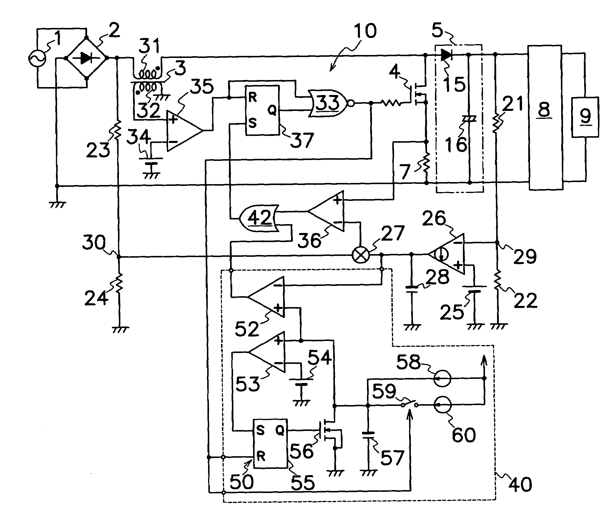
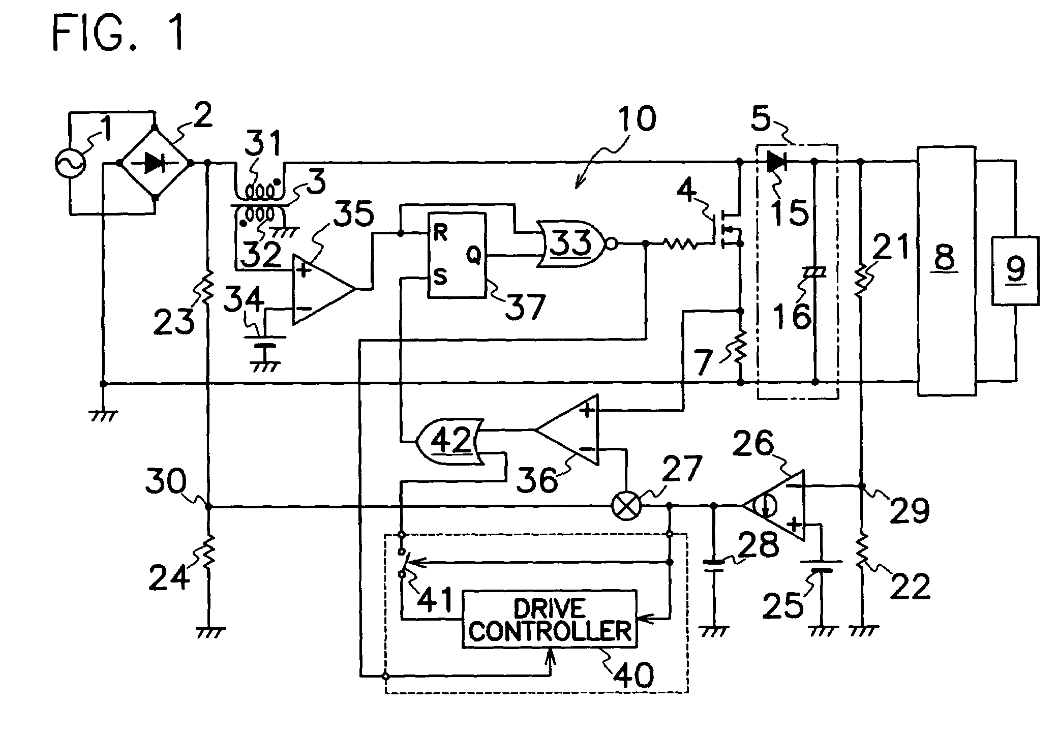
[0023]FIG. 1 is an electric circuit diagram showing the basic concept of the switching power source device according to the present invention. As shown in FIG. 1, the switching power source device according to the present invention, comprises: an OR gate 42 connected between first comparator 36 and RSF / F 37 as a changeover circuit; a drive controller 40 connected in series between a junction of error amplifier 26 and multiplier 27 and OR gate 42 for receiving drive signals to MOS-FET 4; and a switch element 41 connected between an output terminal of drive controller 40 and OR gate 42. FIG. 2 is an electric circuit diagram of drive controller 40.

[0024]In the first embodiment shown in FIG. 2, drive controller 40 comprises a second comparator 52 which has an inverted input terminal connected to junction of error amplifier 26 and multiplier 27 and an output terminal connected to an input terminal of OR gate 42; a level detector 53 which has an inverted input terminal connected to a seco...

second embodiment

[0031]FIG. 6 shows the drive controller in the switching power source according to the present invention wherein a regulatory series circuit of variable current regulator 61 and bipolar transistor 59 as a switch is connected in parallel to capacitor 57 to electrically charge capacitor 57 with a differential current between those flowing through first current regulator 58 and variable current regulator 61 unlike the drive controller shown in FIG. 2. FIG. 7 illustrates a detailed circuit of the drive controller shown in FIG. 6. However, whereas bipolar transistor 59 of FIG. 6 is turned off when NOR gate 33 produces the output of high voltage level, bipolar transistor 59 of FIG. 7 is turned on when NOR gate 33 produces the output of high voltage level. In either of circuits shown in FIGS. 6 and 7, no current flows from current regulator 61 while NOR gate 33 produces the output of high voltage level. Variable current regulator 61 of FIG. 7 comprises a first current mirror circuit 61 whi...


PUM


Abstract

A switching power source device is provided which comprises a drive controller 40 connected between an error amplifier 26 and changeover circuit 37. A second comparator 52 of drive controller 40 compares an output voltage or an equivalent signal thereto from error amplifier 26 with a numerical value from a sweep circuit 57 and produces an output to changeover circuit 37 to stop the on-operation of a switching element 4 and restrict an undesirable rise in output voltage during the light load period when the numerical value exceeds the output voltage or an equivalent signal thereto from error amplifier 26.

Description

TECHNICAL FIELD[0001]This invention relates to a switching power source device used in electronics, in particular, a switching power source device which has an improved power factor and enhanced conversion efficiency in electric power during the light load period under control of excessive output voltage.BACKGROUND OF THE INVENTION[0002]Switching power source devices of improved power factor have been employed in electronics such as office automation facilities and consumer appliances under harmonic current regulations (IEC / EN61000-3-2) and a guideline of harmonics control for household and general electric appliances. For example, U.S. Pat. No. 6,373,735 to Hiroshi Usui, discloses an AC-DC converter which comprises a MOS-FET, a boost circuit having a reactor connected in series to the MOS-FET to produce DC output voltage, and a control circuit for applying drive signals to a gate terminal of the MOS-FET to turn the MOS-FET on and off in order to accumulate and discharge energy in t...

Claims


Application Information

Patent Timeline
Patent Type & Authority Patents(United States)
IPC IPC(8): H02M7/68
CPCH02M3/157H02M3/158E05B49/00E05B17/0083E05B17/0087
Inventor SHIMADA, MASAAKI
Owner SANKEN ELECTRIC CO LTD
Why Eureka
Try Eureka