Parametric audio system

a technology of audio system and parametric wave, applied in direction finders using ultrasonic/sonic/infrasonic waves, mechanical vibration separation, instruments, etc., can solve the problems of difficult to minimize the distortion of regenerated audio signals, 2-5 khz, narrow bandwidth of the piezoelectric transducer used therewith, etc., to achieve sufficient bandwidth, reduce distortion, and increase the bandwidth for generating

Inactive Publication Date: 2008-06-24
POMPEI FRANK JOSEPH
View PDF50 Cites 37 Cited by
  • Summary
  • Abstract
  • Description
  • Claims
  • Application Information

AI Technical Summary

Benefits of technology

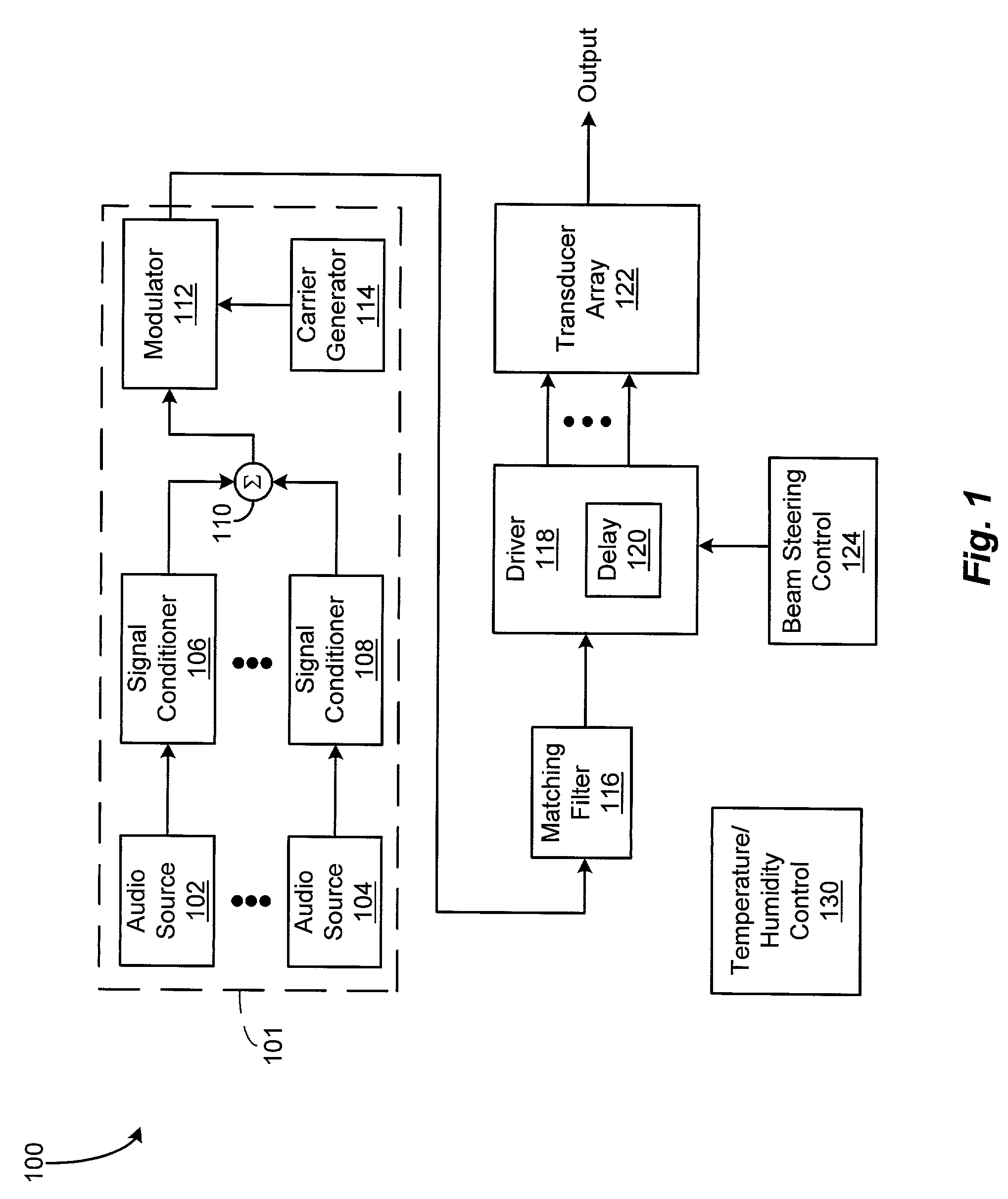
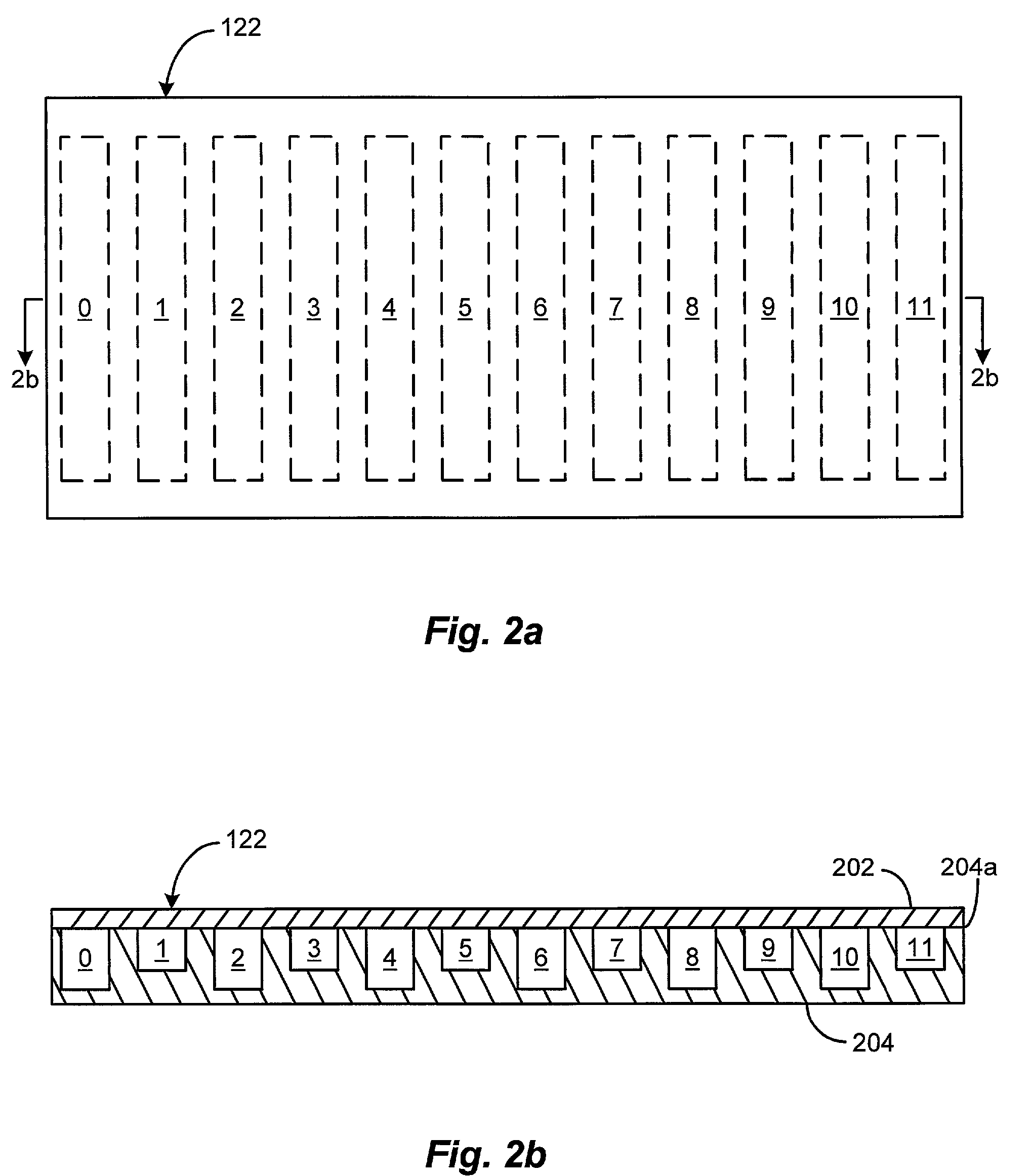
[0009]In accordance with the present invention, a parametric audio system is provided that has increased bandwidth for generating airborne audio signals with reduced distortion. In one embodiment, the parametric audio system includes a modulator for modulating an ultrasonic carrier signal with at least one processed audio signal, at least one driver amplifier for amplifying the modulated carrier signal, and an array of acoustic transducers for projecting the modulated and amplified carrier signal through the air for subsequent regeneration of the audio signal along a selected projection path. Each of the acoustic transducers in the array is a membrane-type transducer. In a preferred embodiment, the membrane-type transducer is a Sell-type electrostatic transducer that includes a conductive membrane and an adjacent conductive backplate. In an alternative embodiment, the Sell-type electrostatic transducer includes a conductive membrane, an adjacent insulative backplate, and an electrode disposed on the side of the insulative backplate opposite the conductive membrane. The backplate preferably has a plurality of depressions formed on a surface thereof near the conductive membrane. The depressions in the backplate surface are suitably formed to set the center frequency of the membrane-type transducer, and to allow sufficient bandwidth to reproduce a nonlinearly inverted ultrasonic signal. Further, the driver amplifier includes an inductor coupled to the capacitive load of the membrane-type transducer to form a resonant circuit. In a preferred embodiment, the center frequency of the membrane-type transducer, the resonance frequency of the resonant circuit formed by the driver amplifier coupled to the membrane-type transducer, and the frequency of the ultrasonic carrier signal are equal to the same value of at least 45 kHz. The array of acoustic transducers is arranged in one or more dimensions and is capable of electronically steering at least one audio beam along the selected projection path. In one embodiment, the acoustic transducer array has a one-dimensional arrangement and is capable of electronically steering at least one audio beam in one (1) angular direction. In another embodiment, the acoustic transducer array has a two-dimensional arrangement and is capable of electronically steering at least one audio beam in two (2) angular directions. In a preferred embodiment, the acoustic transducer array is a one-dimensional linear array that steers, focuses, or shapes at least one audio beam in one (1) angular direction by distributing a predetermined time delay across the acoustic transducers of the array.

Problems solved by technology

One drawback of the above-described conventional parametric audio system is that the piezoelectric transducers used therewith typically have a narrow bandwidth, e.g., 2-5 kHz.
As a result, it is difficult to minimize distortion in the regenerated audio signals.
However, because the typical piezoelectric transducer has a diameter of only about 0.25 inches, it is often necessary to include hundreds or thousands of such piezoelectric transducers in the acoustic transducer array to achieve an optimal acoustic transducer surface area, thereby significantly increasing the cost of manufacture.
Another drawback of the conventional parametric audio system is that the ultrasonic signal is typically directed along the selected projection path by a mechanical steering device.
However, such mechanical steering devices are frequently expensive, bulky, inconvenient, and limited.

Method used


Image

  • Parametric audio system
  • Parametric audio system
  • Parametric audio system

Examples


Embodiment Construction

[0020]U.S. patent application Ser. No. 09 / 300,022 filed Apr. 27, 1999 is incorporated herein by reference.

[0021]U.S. Provisional Patent Application No. 60 / 176,140 filed Jan. 14, 2000 is incorporated herein by reference.

[0022]Methods and apparatus are disclosed for directing ultrasonic beams modulated with audio signals through the air for subsequent regeneration of the audio signals along selected paths of projection. The presently disclosed invention directs such modulated ultrasonic beams through the air by way of a parametric audio system configured to provide increased bandwidth and reduced distortion in an implementation that is less costly to manufacture.

[0023]FIG. 1 depicts a block diagram of an illustrative embodiment of a parametric audio system 100 according to the present invention. In the illustrated embodiment, the parametric audio system 100 includes an acoustic transducer array 122 comprising a plurality of acoustic transducers arranged in a one, two, or three-dimensi...


PUM


Abstract

A parametric audio system having increased bandwidth for generating airborne audio signals with reduced distortion. The parametric audio system includes a modulator for modulating an ultrasonic carrier signal with a processed audio signal, a driver amplifier for amplifying the modulated carrier signal, and an array of acoustic transducers for projecting the modulated and amplified carrier signal through the air along a selected projection path to regenerate the audio signal. Each of the acoustic transducers in the array is a membrane-type transducer. Further, the acoustic transducer array is a phased array capable of electronically steering, focusing, or shaping one or more audio beams.

Description

CROSS REFERENCE TO RELATED APPLICATIONS[0001]This application is a continuation-in-part application of prior U.S. patent application Ser. No. 09 / 300,022 filed Apr. 27, 1999 entitled PARAMETRIC AUDIO SYSTEM.[0002]This application claims priority of U.S. Provisional Patent Application No. 60 / 176,140 filed Jan. 14, 2000 entitled PARAMETRIC AUDIO SYSTEM.STATEMENT REGARDING FEDERALLY SPONORED RESEARCH OR DEVELOPMENT[0003]N / ABACKGROUND OF THE INVENTION[0004]The present invention relates generally to parametric audio systems for generating airborne audio signals, and more specifically to such parametric audio systems that include arrays of wide bandwidth membrane-type transducers.[0005]Parametric audio systems are known that employ arrays of acoustic transducers for projecting ultrasonic carrier signals modulated with audio signals through the air for subsequent regeneration of the audio signals along a path of projection. A conventional parametric audio system includes a modulator for mo...

Claims


Application Information

Patent Timeline
Patent Type & Authority Patents(United States)
IPC IPC(8): H04R3/00H04R19/00B06B1/02B06B1/06G10K15/02H04B11/00
CPCB06B1/0292B06B1/0622G10K15/02B06B1/0692H04S2400/09H04R2217/03
Inventor POMPEI, FRANK JOSEPH
Owner POMPEI FRANK JOSEPH
Why Eureka
Try Eureka