Chemical probe using field-induced droplet ionization mass spectrometry

a droplet ionization and chemical probe technology, applied in the field of interfacial chemical probes, can solve the problems of kilovolt differences and electrosprays at the nozzle, low ionization mass spectrometry, and low ionization mass spectrometry, and achieve the effects of reducing the ionization intensity of the sample, and reducing the ionization intensity

Inactive Publication Date: 2008-07-01
CALIFORNIA INST OF TECH
View PDF3 Cites 11 Cited by
  • Summary
  • Abstract
  • Description
  • Claims
  • Application Information

AI Technical Summary

Problems solved by technology

Small statistical differences in charging between water dripping from the nozzles quickly led to kilovolt differences and electrosprays at the nozzles.
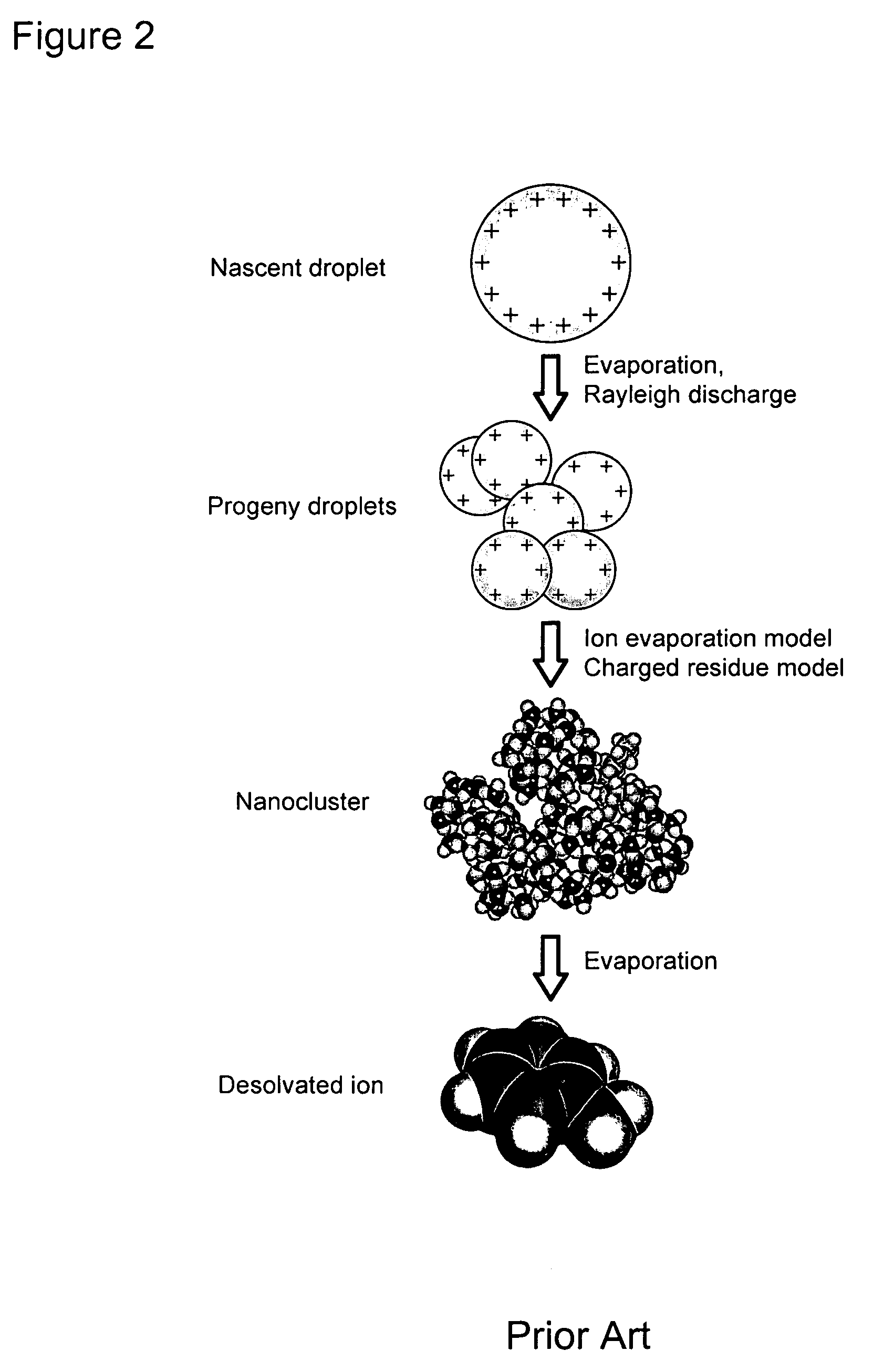
Despite a rigorous prediction of when the event occurs, Rayleigh's analysis does little to describe the dynamics of the discharge event.
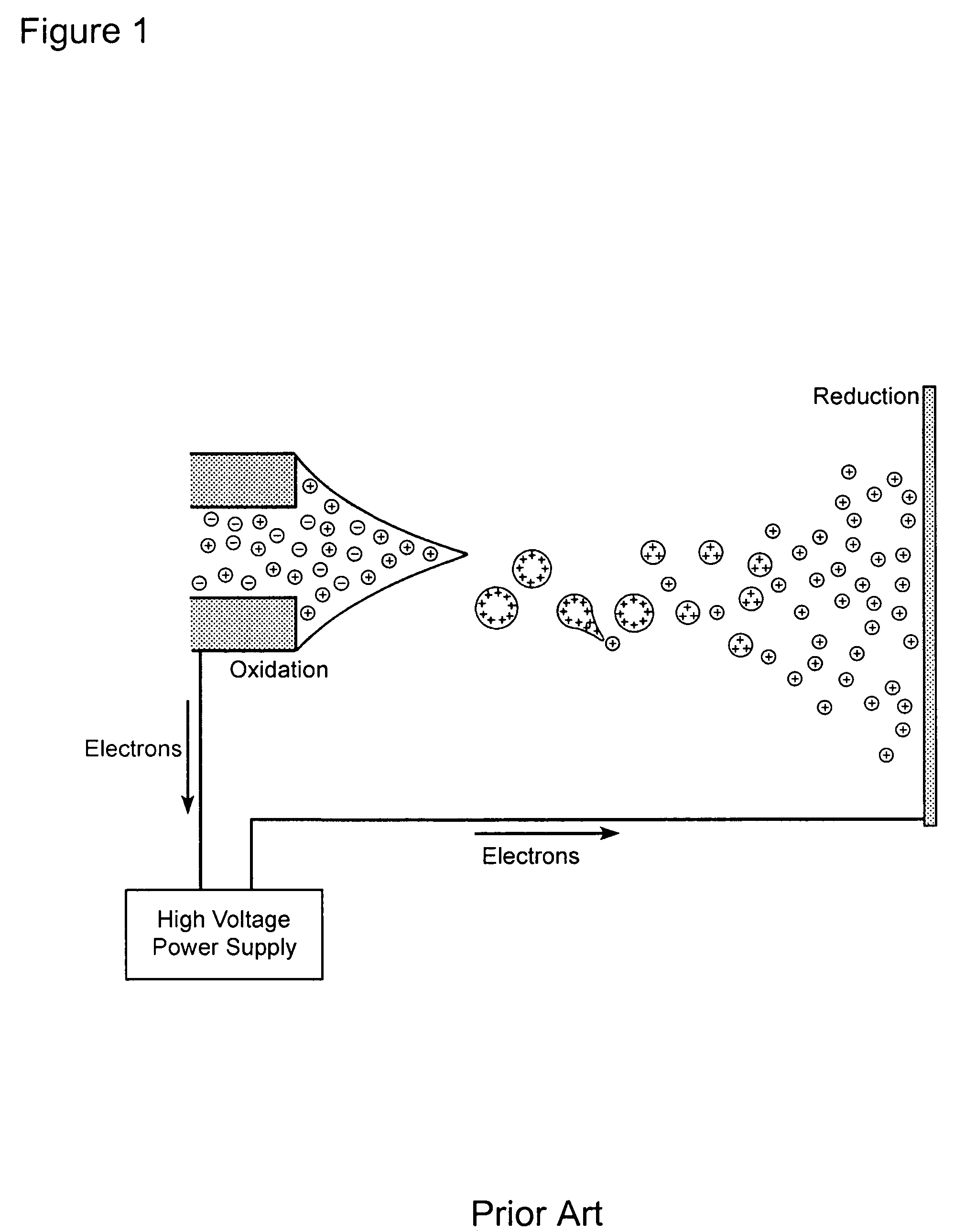
In this case, the electrical pressure of high charge drives an instability leading to jetting of fine jets of charged progeny droplets.
However, electrical pressure leading to droplet instability may also be due to an applied strong electric field.
Although chemistry on and within liquid droplets is ubiquitous in nature and anthropomorphic processes, investigators have only begun to understand and harness such reactions.
Specifically, because of their inherently transient nature, these droplet streams are difficult to manipulate and utilize as chemical probes.
In addition, although Taylor's analysis predicts the field necessary for droplet instability and jetting through Equation (2), the analysis does not predict the timescales or the dynamics of the process.

Method used


Image

  • Chemical probe using field-induced droplet ionization mass spectrometry
  • Chemical probe using field-induced droplet ionization mass spectrometry
  • Chemical probe using field-induced droplet ionization mass spectrometry

Examples


example 1

Discussion of Dynamics Example 1

[0094]First an investigation was undertaken to determine the dynamics of droplets in field below Ec0. FIG. 9 highlights a sequence of droplets in a 2.00×10⁶ V m−1 electric field. Initially, γ(0 μs)=1 corresponding to the spherical droplet (a). A damped shape oscillation is marked by increasing aspect ratios in (b)-(e), decreasing aspect ratios in (e)-(i), and increasing again in (j). FIG. 10 highlights this trend in plots of γ versus the time in the electric field for four field strengths below Ec0. Each point represents the average aspect ratio for approximately ten images at each respective time, and is fit to the exponentially damped sine function (6). The fitted equilibrium aspect ratios, γ∞, strictly increase as the electric field increases and are in excellent agreement with Taylor's theoretical model, Equation (3), for each respective electric field.

[0095]FIG. 11 compares the fitted oscillation frequencies from this work (round markers) with th...

example 2

Discussion of Dynamics Example 2

[0096]The second investigation was undertaken to determine the dynamics of neutral droplets in field above Ec0. FIG. 12 shows 225 μm diameter droplets symmetrically elongating and jetting at two field strengths. Droplets oscillate at 2.14×10⁶ V m−1, as shown by FIG. 11 and undergo FIDI in a 2.18×10⁶ V m−1 field, in good agreement with the value of Ec0 predicted by Equation (2). In a 2.18×10⁶ V m−1 field, jetting begins after 650 μs (FIG. 12e), whereas jetting occurs as early as 350 μs in a 2.46×10⁶ V m−1 field (FIG. 12j). Thus, the 13% increase in the electric field above Ec0 accelerates the elongation and reduces the time to form jets by 46%. FIG. 13 graphs γ(t) for fields between 2.18 and 2.42×10⁶ V m−1 as well as the fitted oscillation γ(t) at 2.14×10⁶ V m−1 reproduced from FIG. 11. FIG. 13 illustrates this reduction in time to achieve jetting which results from increasing the applied field. For droplets at Ec0, conical shapes begin to form at aspe...

example 3

Discussion of Dynamics Example 3

[0100]The third investigation was undertaken to determine the dynamics of charged droplets in field above Ec0. FIGS. 14 and 15 show asymmetrical stretching and jetting from charged 225 μm methanol droplets. FIGS. 14a-e shows droplets carrying a charge 0.04 qR in a 2.16×10⁶ V m−1 field and 0.09 qR droplets in a 2.14×10⁶ V m−1 field in frames (f)-(j). In both cases, droplets are exposed to the minimum field required for jetting, Ecq, for each respective q. Similarly, FIG. 15a-h displays a sequence of 0.13 qR droplets at their critical field of 2.09×10⁶ V m−1. The non-linear trend in decreasing critical fields agrees with finite-element calculations. (See, e.g., Basaran, O. A.; Scriven, L. E. Phys. Fluids A 1989, 1, 799, the disclosure of which is incorporated herein by reference.) Similarly, the time to initiate jetting decreases as net charge increases. At 0.04 qR, jet formation occurs at 650 μs as shown in FIG. 14e which is the same timescale observed...


PUM


Abstract

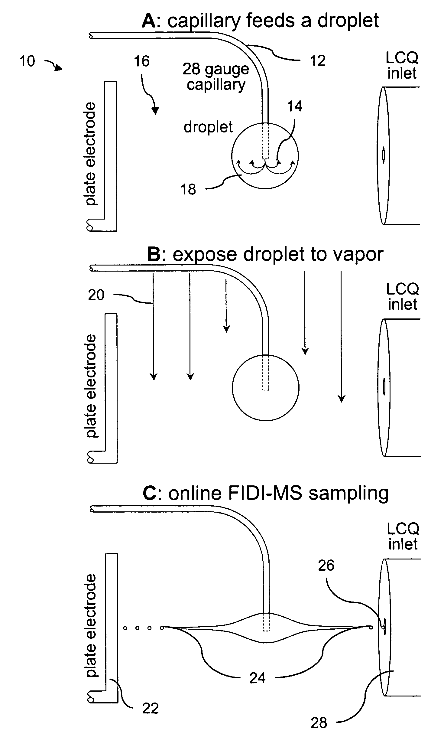
A method and apparatus for probing the chemistry of a single droplet are provided. The technique uses a variation of the field-induced droplet ionization (FIDI) method, in which isolated droplets undergo heterogeneous reactions between solution phase analytes and gas-phase species. Following a specified reaction time, the application of a high electric field induces FIDI in the droplet, generating fine jets of highly charged progeny droplets that can then be characterized. Sampling over a range of delay times following exposure of the droplet to gas phase reactants, the spectra yield the temporal variation of reactant and product concentrations. Following the initial mass spectrometry studies, we developed an experiment to explore the parameter space associated with FIDI in an attempt to better understand and control the technique. In an alternative embodiment of the invention switched electric fields are integrated with the technique to allow for time-resolved studies of the droplet distortion, jetting, and charged progeny droplet formation associated with FIDI.

Description

CROSS-REFERENCE TO RELATED APPLICATIONS[0001]This application claims priority based on U.S. provisional application No. 60 / 665,673, filed Mar. 28, 2005, the disclosure of which is incorporated herein by reference.STATEMENT OF FEDERAL FUNDING[0002]The Government has certain rights in this invention, based on support for the work under a grant from the National Science Foundation (Grant No. CHE-0416381).FIELD OF THE INVENTION[0003]The current invention is directed generally to an interfacial chemical probe; and more particularly to an interfacial chemical probe that uses field-induced droplet ionization mass spectrometry.BACKGROUND OF THE INVENTION[0004]In the past twenty years, charged droplets and strong electric fields have quietly revolutionized chemistry. In combination with an atmospheric-sampling mass spectrometer, charged droplets containing biomolecules or polymers have become a source for desolvated, gas-phase ions of these analytes. The process by which charged droplets eva...

Claims


Application Information

Patent Timeline
Patent Type & Authority Patents(United States)
IPC IPC(8): H01J49/04H01J49/10
CPCH01J49/165
Inventor GRIMM, II, RONALD L.BEAUCHAMP, JESSE L.
Owner CALIFORNIA INST OF TECH
Why Eureka
Try Eureka