Phase locked loop

a phase locked loop and phase noise technology, applied in pulse automatic control, oscillation generator, resonance circuit tuning, etc., can solve the problems of affecting the smooth operation the inability to meet the needs of modern multi-slot communication systems, and the susceptibility of the phase noise of the phase lock loop

Active Publication Date: 2008-07-01
NOKIA TECHNOLOGLES OY
View PDF3 Cites 12 Cited by
  • Summary
  • Abstract
  • Description
  • Claims
  • Application Information

AI Technical Summary

Benefits of technology

[0014]The invention allows the loop filter to be advantageously modified. The loop filter, connected to a node between the phase detector and the voltage controlled oscillator, no longer needs to include a series combination of resistor and capacitor. The loop filter may consist of a single, low value capacitor. The reduced capacitance results in an improved settling time.
[0019]Embodiments of the invention reduce any frequency over shoot when the output frequency is changed. This allows voltage controlled oscillators of reduced frequency sensitivity to be used. Therefore, a lower sensitivity VCO can be used, which advantageously reduces phase noise.
[0020]The use of both a variable delay and a discrete delay, allows the introduction of a large delay without having to have a mechanism for introducing a large continuous delay. The variable delay component can therefore operate over a reduced time delay range, which means that it can have a reduced sensitivity and therefore is less susceptible to introducing phase noise.

Problems solved by technology

Such phase locked loops suffer from a number of problems.
One problem is a long settling time after a change in frequency which may make it unsuitable for modern multi-slot communication systems, in which changes in frequency occur at higher rates than in non multi-slot communication systems.
Another problem is the PLL's susceptibility to phase noise as the sensitivity of the VCO increases.

Method used


Image

  • Phase locked loop
  • Phase locked loop
  • Phase locked loop

Examples


Embodiment Construction

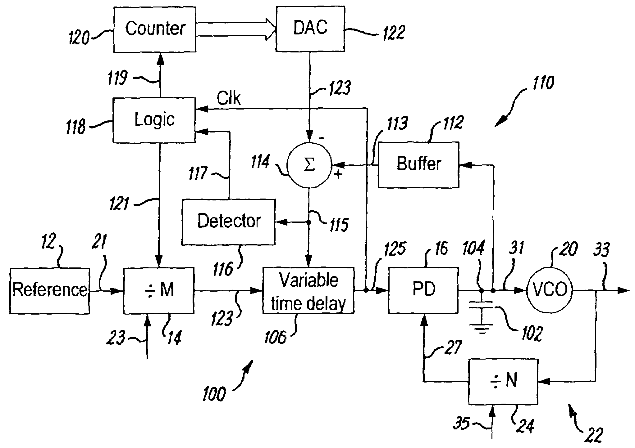
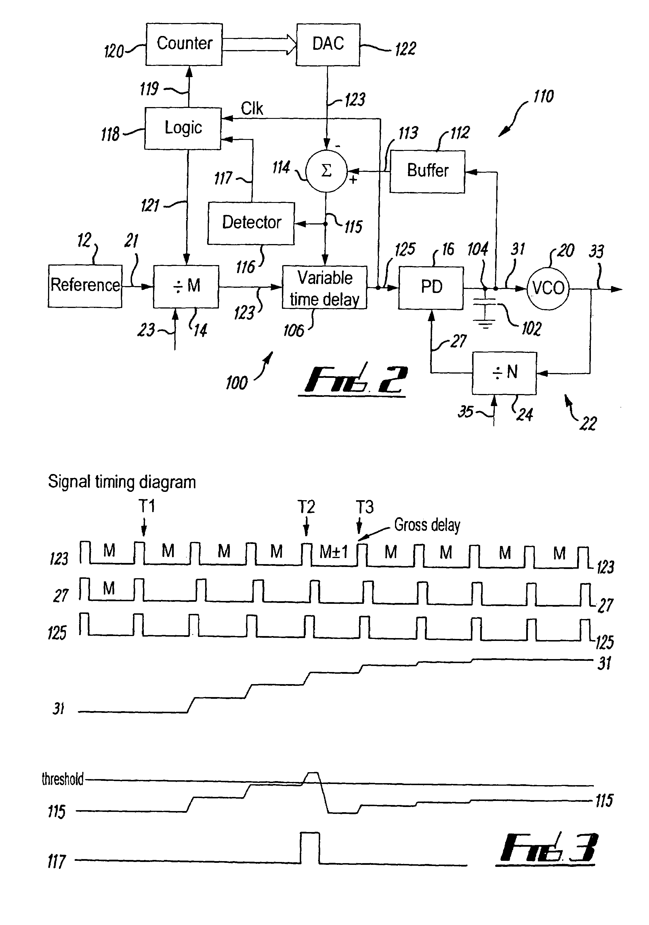
[0027]FIG. 2 illustrates an adapted phase locked loop (PLL) 100 with a delay locked loop (DLL) wrapped around the phase detector 16.

[0028]The adapted PLL 100 differs from the PLL 10 of FIG. 1 in that:[0029]a) the multi-component loop filter has been replaced by a simplified loop filter, which in this example comprises a single capacitor 102 connected between a node 104, between the phase detector 16 and the VCO 20, and ground.[0030]b) it additionally has a variable delay component 106 connected between the first counter 14 and the phase detector 16[0031]c) it has a feedback path from the phase detector 16 back to the variable delay component 106 and the reference counter 14 so as to form a delay locked loop (DLL) 110 wrapped around the phase detector 16. The feedback path takes as an input the output of the phase detector 16, and provides a first delay control signal 121 to the reference counter 14 and provides a second delay control signal 115 to the variable delay component 106.

[0...


PUM


Abstract

A phase locked loop circuit, for providing an oscillating output signal at an output frequency, including: a reference counter; a loop counter; a phase detector having a first input coupled to the reference counter and a second input coupled to the loop counter; a voltage controlled oscillator having an input coupled to the output of the phase detector and an output for providing the oscillating output signal; a feedback loop coupling the output of the voltage controlled oscillator to the input of the loop counter; and delay circuitry, including a feedback loop, arranged to introduce a discrete delay into the output of the loop counter and / or the reference counter.

Description

FIELD OF THE INVENTION[0001]Embodiments of the present invention relate to phase locked loops.BACKGROUND TO THE INVENTION[0002]FIG. 1 illustrates a typical phase locked loop (PLL) 10. The PLL comprises in order: a reference oscillator 12, a reference counter 14, a phase detector 16, a loop filter 18, a voltage controlled oscillator 20, and a feedback loop 22 from the VCO 20 through a loop counter 24 to the phase detector 16.[0003]Reference oscillator supplies a reference frequency signal 21, having a frequency Fref, to the reference counter 14. The reference counter operates as a divider and produces an output pulse when it has counted M input pulses of the reference frequency signal 21. The value of M can be varied via an input control signal 23. Thus the first counter produces a reduced frequency input signal 25 which has a frequency 1 / M Fref.[0004]The phase detector 16 receives the reduced frequency input signal 25 at one input and a reduced frequency output signal 27 at the othe...

Claims


Application Information

Patent Timeline
Patent Type & Authority Patents(United States)
IPC IPC(8): H03L7/00H03L7/081H03L7/197
CPCH03L7/197H03L7/081H03L7/23H03L7/18
Inventor BEESON, PETER
Owner NOKIA TECHNOLOGLES OY
Why Eureka
Try Eureka