

Fiber-optic assay apparatus based on phase-shift interferometry
a fiber optic assay and phase-shift interferometer technology, applied in the field of fiber optic assay apparatus based on phase-shift interferometer, can solve the problems of changing the interference the coupling of the reflected beam back into the optical fiber, and the interference change between the two reflected beams, so as to increase the thickness of the first reflecting layer
- Summary
- Abstract
- Description
- Claims
- Application Information
AI Technical Summary
Benefits of technology
Problems solved by technology
Method used
Image

Examples
example 1
Small Molecule-protein Binding Reaction
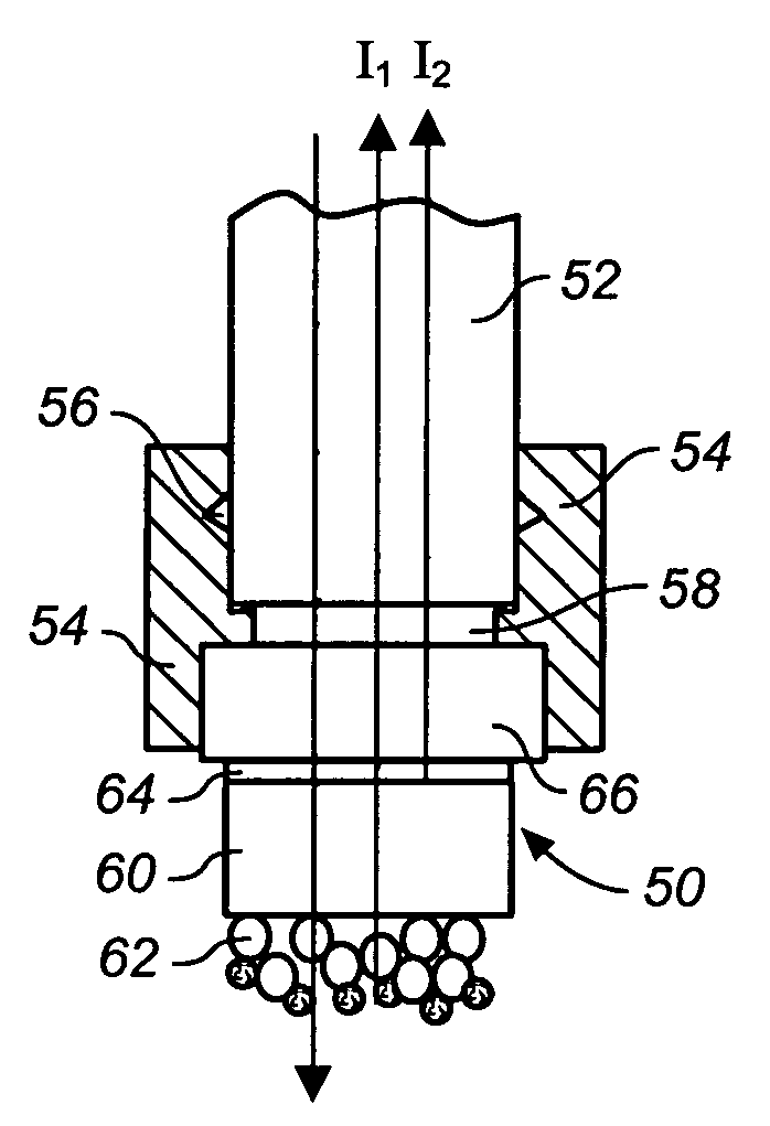
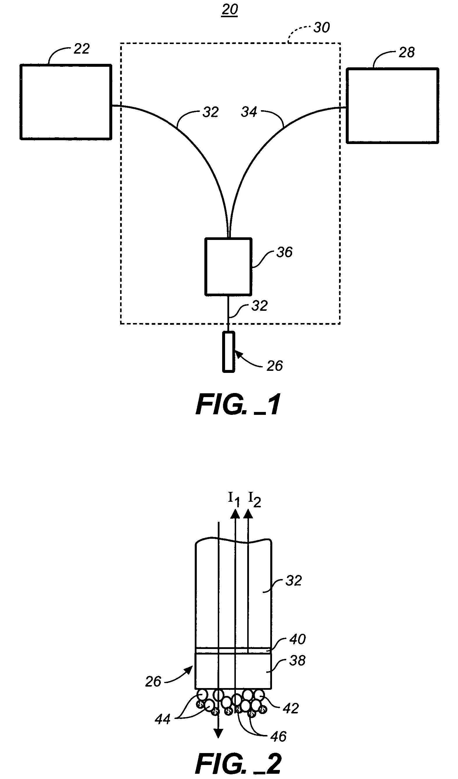
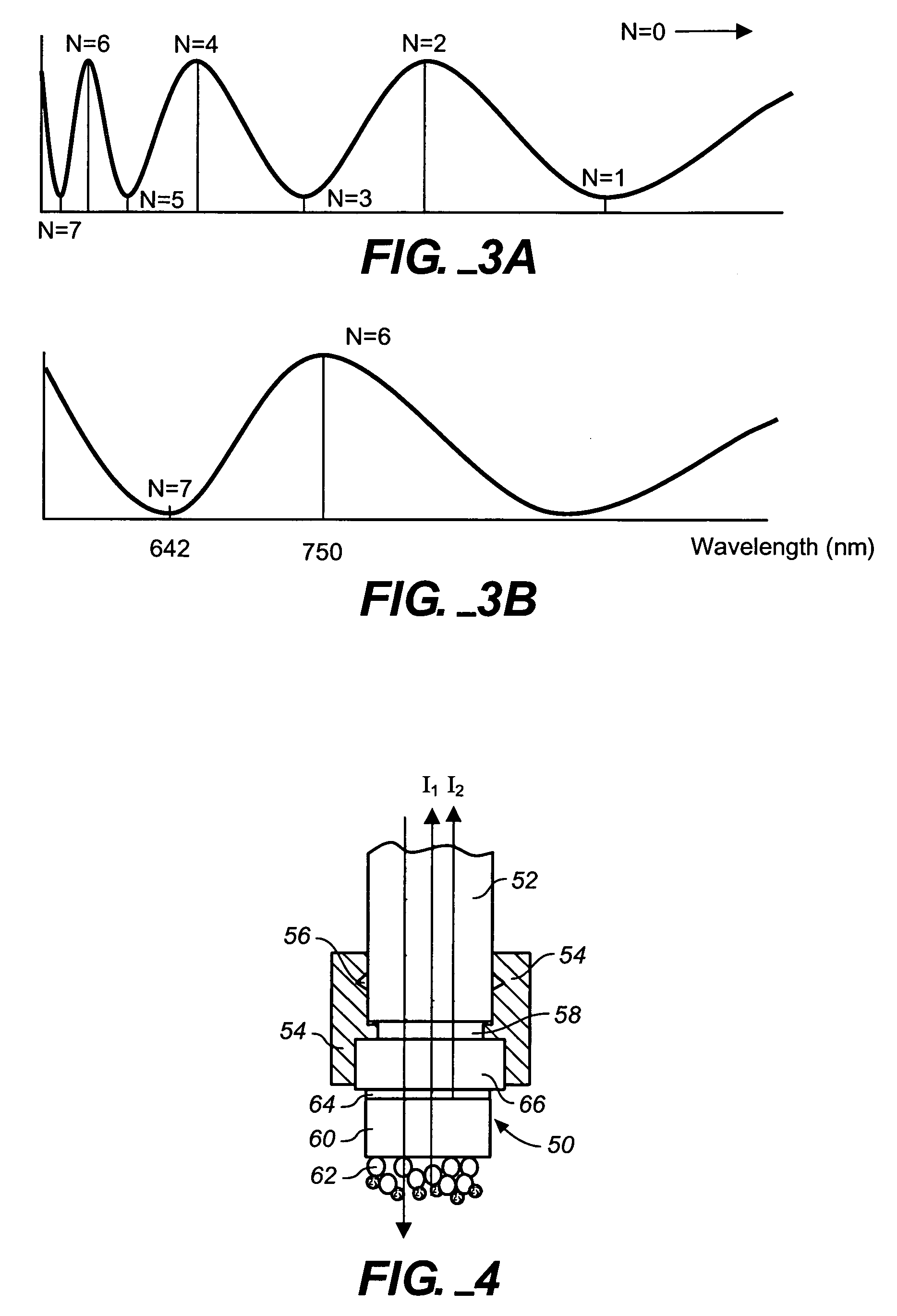
[0100]This example demonstrates the capability to detect the binding of protein to small molecule immobilized on a sensor tip and subsequent bindings of multiple antibodies. The two-layer configuration on the tip of an optic fiber is used for this test. The thickness of the first Ta2O5 layer is 25 nm and the thickness of the second SiO2 layer is 770 nm. The fiber was purchased from Ocean Optics (Dunedin, Fla.). It was manually cut into segments that are 40 mm long. Both ends of these segments were polished to standard mirror surface quality. The polishing method used here was exactly the same as those for optical lenses and mirrors. One surface of these fiber segments was outsourced to an optical coating house for Ta2O5 layer and SiO2 layer. This vendor employed an ion-beam assisted physical vapor deposition (IAPVD) coater made by Leybold. IAPVD is a commonly used coating technique for anti-reflection and optical filters. The experimental steps...
example 2
Biomolecular Interaction Analysis of Kinetics and Affinity of Biomolecular Interactions
[0106]This example illustrates use of the invention to carry out a biomolecular interaction analysis (BIA) measuring kinetics and affinity of biomolecular interactions. The same tip configuration as described in Example 1 was used. The experimental steps included the following (all steps are performed at room temperature unless otherwise noted):
[0107]Mercaptosilane coated tips were prepared using the following procedure. Clean, dry fibers were incubated in a mixture of Toluene: hexanoic acid: mercaptopropyltrioxysilane (10:2:1 volumetric ratio) at room temperature for 24 hours. The fibers were rinsed 2× with 10 mL toluene for 5 minutes each. The fibers were then rinsed 1× with 10 mL of ethanol and dried under a stream of argon and stored at ambient conditions.
[0108]The biosensor tip was first derivatized by immersion in a with 10 μg / ml solution of rabbit-IgG (Jackson ImmunoResearch, West Grove, Pa...
example 3
Calculating Affinity Constants from Antibody-antigen Binding and Release Curves
[0113]This experiment demonstrates the calculation of affinity constants from measuring on and off curves for two antibodies and their antigen. The proprietary antibodies were labeled as Ab-1 and Ab-2. The molecular weight of the antigen was about 30 kilodaltons. The same tip configuration as described in Example 1 was used. The same mercaptosilane fiber preparation as described in Example 2 was used. The experimental steps included (all steps are performed at room temperature unless otherwise noted):
[0114]The fiber tip was activated for covalent attachment of the antigen. Mercaptosilane coated fibers were activated by immersing the sensor tips in 50 μL of a 50 mg / mL solution of sulfo-SMCC (Pierce Biotechnology, Rockford Ill.; cat # 22322) in DMF (Sigma-Aldrich Chemical Company, St Louis, Mo.; cat # 494488) at for 2 hours. The sensor tips were rinsed briefly in DMF and dried;
[0115]The antigen was covalent...
PUM
| Property | Measurement | Unit |
|---|---|---|
| refractive index | aaaaa | aaaaa |
| thickness | aaaaa | aaaaa |
| thickness | aaaaa | aaaaa |
Abstract
Description
Claims
Application Information