Eureka AIR delivers breakthrough ideas for toughest innovation challenges, trusted by R&D personnel around the world.

Optical communication management systems

a communication management system and optical communication technology, applied in the field of optical communication management systems, can solve the problems of high cost per customer flow, and increased cost to service providers, and achieve the effect of greater sensitivity to changes in optical characteristics

Inactive Publication Date: 2008-07-01
MANIFOLD ROBERT H
View PDF32 Cites 23 Cited by
  • Summary
  • Abstract
  • Description
  • Claims
  • Application Information

AI Technical Summary

Benefits of technology

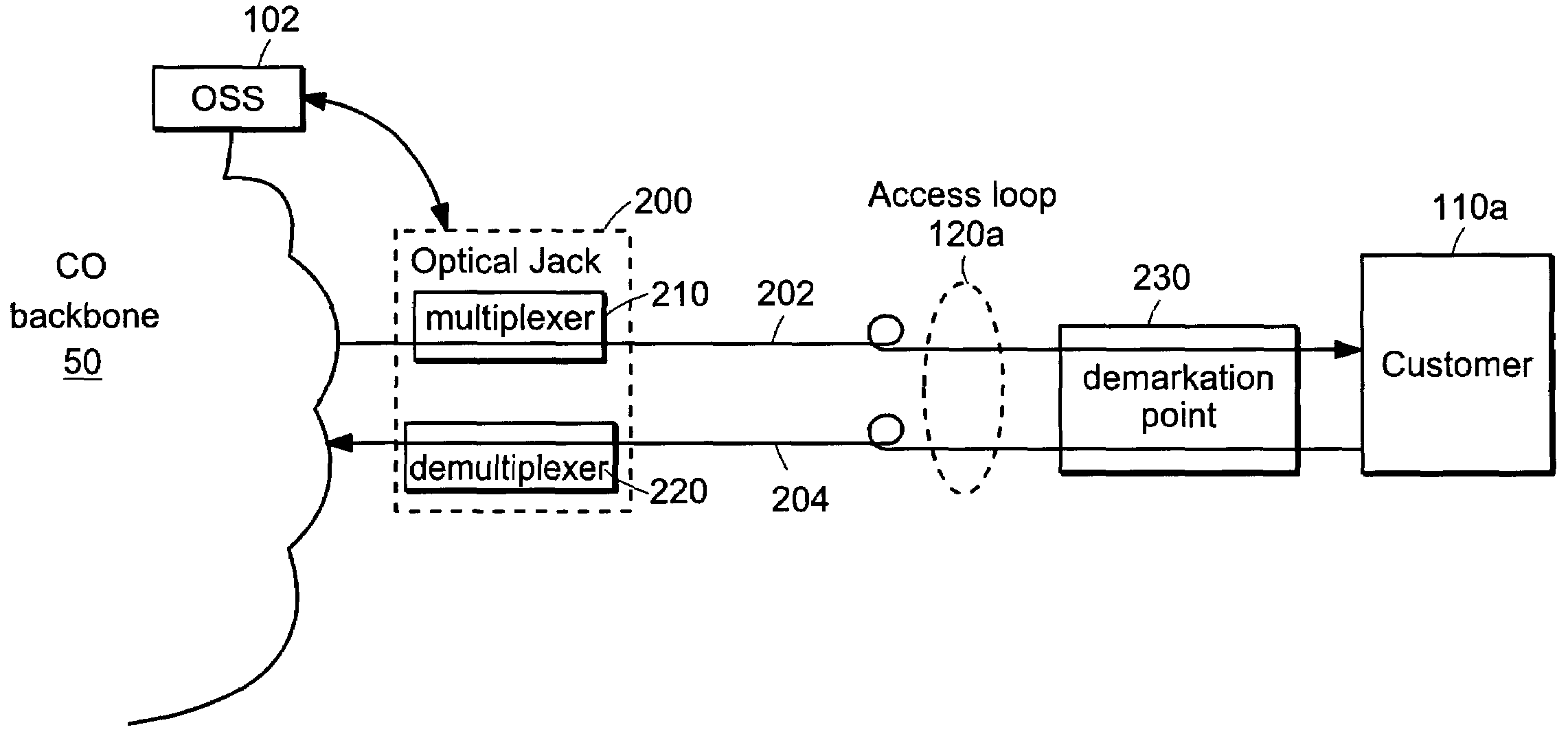
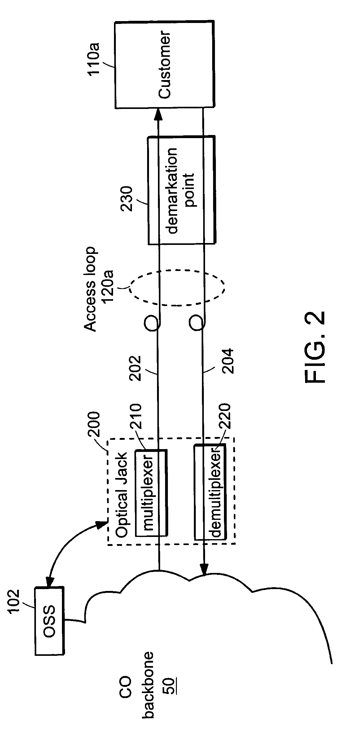
[0006]Costs of providing optically delivered services to enterprise customers can be reduced; i) by separating the optical transport function from the optical service being delivered over the optical medium; ii) by simplifying the optical transport equipment required at the central office (CO) and at the customer premise; and iii) by interfacing to the OSS systems in the same way as the existing transport equipment.
[0017]A forward error correcting protocol may also be implemented across the OMMS path between optical jacks to ensure that end to end communications can be maintained even though the optical path is incurring errors. The error correction protocol would provide additional management information relative to error counts to complement those metrics available from the error detection inherent in the optical medium management signal. These modes of operation provide greater sensitivity to changes in the optical characteristics of the optical medium.

Problems solved by technology

The cost per customer traffic flow is therefore low due to the amortization of the high equipment costs across the large number of flows.
The cost per customer flow is higher than in the backbone because the cost of the transport equipment is amortized over a smaller number of flows.
Equipment that does not provide performance data in the formats required by these OSS, and hence does not readily integrate, represents an added cost to the service providers.

Method used


Image

  • Optical communication management systems
  • Optical communication management systems
  • Optical communication management systems

Examples


Embodiment Construction

[0038]A description of preferred embodiments of the invention follows.

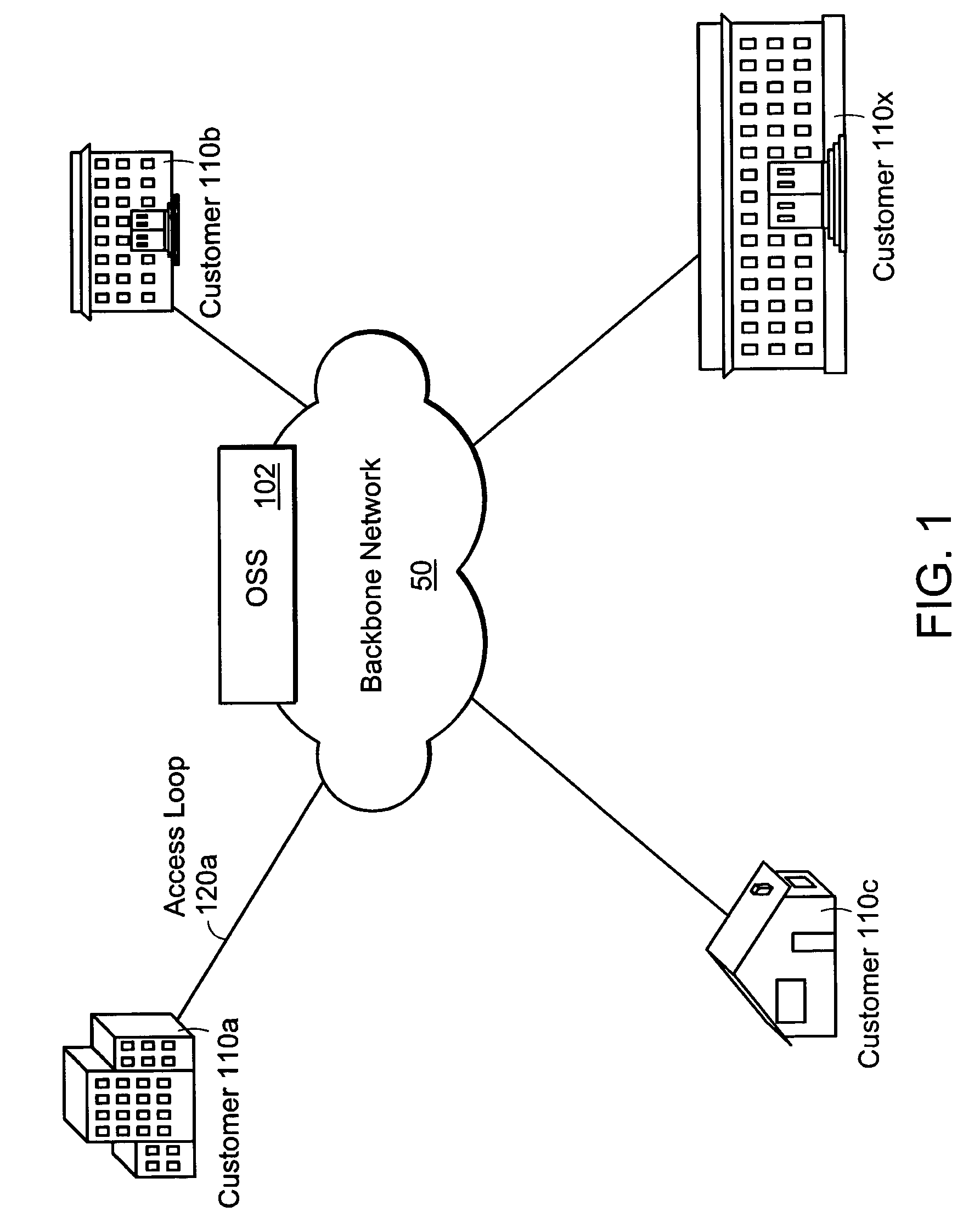
[0039]FIG. 1 is a schematic diagram of a general optical networking environment. Backbone network 50 is a web of tightly coupled predominantly fiber-based networks, with well-orchestrated points of hand-off between various backbone providers, telecommunication companies, and other parties. The operation of backbone network 50 is typically overseen by Operation Support Systems (OSS) 102, providing visibility into the network for Network Operation Centers (NOC's), central office (CO) technicians, and a range of planning and business processes requiring status and use of information relating to the network. The OSS in support of NOC's within operational networks are typically mission-critical, in that they are required to provide responses within minutes or even seconds of a network interruption. Such response may include re-routing or cutting back on traffic, attempting repair of the faulty point, or at least report...


PUM


Abstract

An optical medium, whether inside or outside an internet / telecommunications backbone, is managed using a management signal at a wavelength which is distinct from wavelengths of service signals. A multiplexer multiplexes the management signal onto the optical medium, after which a demultiplexer demultiplexes the management signal for analysis. Performance of customer channels may be inferred from performance of the management signal.

Description

RELATED APPLICATION[0001]This application claims the benefit of U.S. Provisional Application No. 60 / 368,784, filed Mar. 28, 2002. The entire teachings of the above application are incorporated herein by reference.BACKGROUND OF THE INVENTION[0002]A telecommunications network can be viewed as consisting of three main sections: the backbone network, the metro network and the access network. The backbone network connects major switching centers typically located in major cities. The metro network connects a backbone switching center to smaller switching centers located within a metropolitan area, i.e. within a city. The access network connects end user customers to the switching centers of the metro network.[0003]In the backbone the traffic of tens of thousands to millions of customers is aggregated (multiplexed) onto the optical transport equipment that forms the interconnections between switching centers. The cost per customer traffic flow is therefore low due to the amortization of t...

Claims


Application Information

Patent Timeline
IPC IPC(8): H04B10/08H04J14/00H04J3/14H04J14/02H04Q11/00
CPCH04J14/025H04J14/0227H04J14/0282H04J14/0283H04J14/0284H04Q11/0062H04J14/0246H04J14/0226H04J3/14H04J2203/006H04Q2011/0069H04Q2011/0079H04Q2011/0081H04Q2011/0083H04Q2011/0088
Inventor MANIFOLD, ROBERT H.
Owner MANIFOLD ROBERT H
Why Eureka
Eureka Blog
Learn More