Cutting tool and cutting machine

a cutting machine and cutting tool technology, applied in the field of cutting tools and cutting machines, can solve the problems of deteriorating machining accuracy, abrasion and breakage of tools, and above-mentioned conventional tools, and achieve the effect of simple structure and simple structur

Inactive Publication Date: 2008-07-08
KONICA MINOLTA OPTO
View PDF4 Cites 28 Cited by
  • Summary
  • Abstract
  • Description
  • Claims
  • Application Information

AI Technical Summary

Benefits of technology

[0009]The present invention has been attempted to solve the above-noted problems involved in the conventional cutting tools. Thus, an object of the invention is to provide a cutting tool and a cutting machine capable of supplying cutting fluid to an edge or to a working point at a tip of the edge of the tool surely with simple structure.
[0012]According to the present invention, the tip corresponding to a working point is composed by plural faces and edges of the plural faces. Groove shape is formed on at least one of the plural faces. When cutting fluid is supplied to the face with groove geometry externally thereon, the fluid flows along the groove shape. Suppose that the groove shape is formed to head for the tip, cutting fluid is guided to the tip. Thereby, cutting fluid is surely supplied to an edge of the tool or to a working point at a tip of it with simple structure.
[0013]The inventive cutting tool and cutting machine thus can supply cutting fluid to an edge of the tool or to a working point at a tip of it surely with simple structure.

Problems solved by technology

That is, if cutting fluid does not reach a working point when fine processing is done, shortage of the cutting fluid can possibly cause abrasion and breakage of the tool.
If the abraded or broken tool keeps on cutting operation, machining accuracy deteriorates.
However, the above-mentioned conventional tools have had the following problems.
Therefore, cutting fluid is hard to go into a narrow space between the tool and the working object.
Consequently, there arises a problematic case that cutting fluid is not constantly supplied to the working point appropriately.
On that account, shortage of cutting fluid even for an instant can possibly cause damage to the tool.
Furthermore, relating to another conventional method to provide a cutting fluid passage inside of the tool, as disclosed in the Publication No. 8-25111, it is difficult to design and form the passage and a supply route of cutting fluid.
Especially for the case of fly-cut method and the like wherein a cutting tool is moved, special structure for cutting fluid supply is required, which is problematic.

Method used


Image

  • Cutting tool and cutting machine
  • Cutting tool and cutting machine
  • Cutting tool and cutting machine

Examples


first embodiment

[0021]A first embodiment of the present invention will be described in detail below with reference to the accompanying drawings. The first embodiment is an application of the present invention to a cutting tool used for lathing and for fly-cut processing.

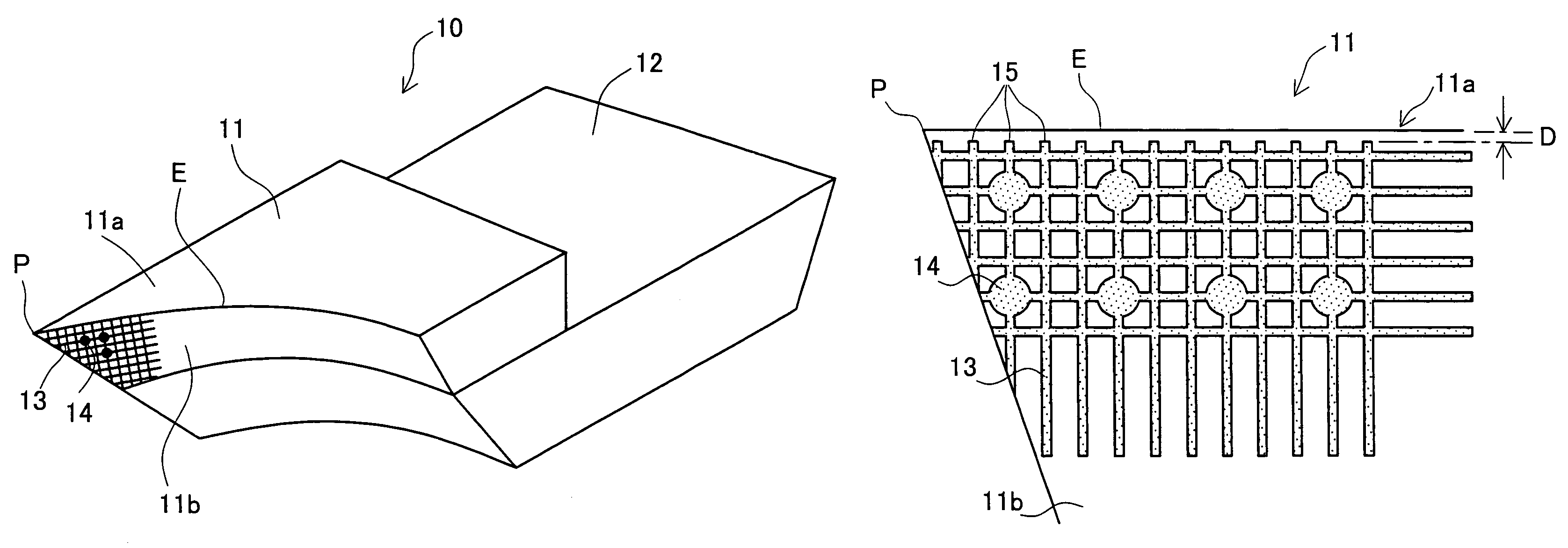
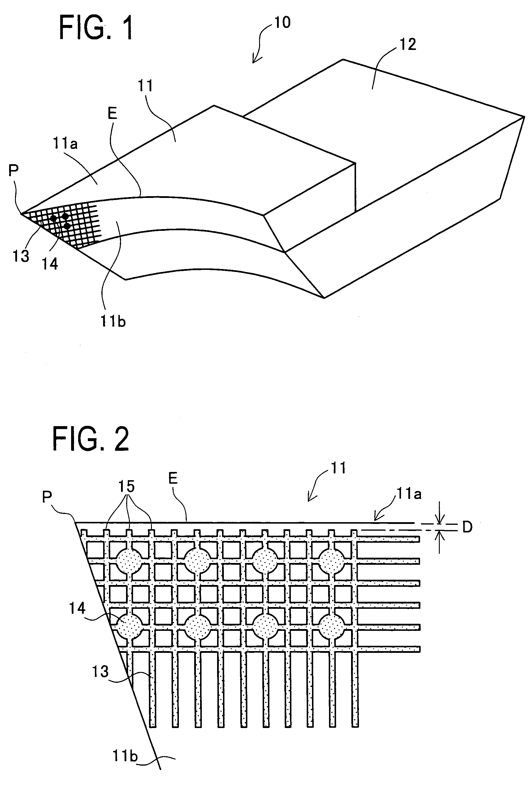
[0022]As shown in FIG. 1, a cutting tool 10 of the first embodiment is constituted by mounting a cutting blade 11 on a blade holder 12. In FIG. 1, an upper face and a front face of the cutting blade 11 correspond to a cutting face 11a and a flank face 11b, respectively. That is, a tip at left front side in FIG. 1 corresponds to a working point P when used. The flank face 11b is a curved face. A rear face of the cutting blade 11, hidden behind the cutting face 11a in FIG. 1, is also a flank face, but not a curved face. The cutting blade 11 is a single crystal diamond blade for fine cutting of μm-order.

[0023]As shown in FIGS. 1 and 2, crossing grid patterned grooves 13 are formed on the flank face 11b of the cutting blade 11, in the v...

second embodiment

[0032]A second embodiment of the present invention will be described in detail below with reference to the accompanying drawings. The second embodiment is an application of the present invention to a cutting tool used for lathing and for fly-cut processing.

[0033]An external form of a cutting blade 31 of this embodiment is similar to that of the cutting blade 11 directed the first embodiment. Similar to the cutting blade 11, the cutting blade 31 has a working point P at the tip constituted by a cutting surface 31a and a flank face 31b. As shown in FIG. 6, there are formed a dent portion 32 and plural grooves 33 reaching the working point P from the concave portion 32, on the flank face 31b. The second embodiment intends to supply cutting fluid to the working point P intensively.

[0034]Similar to the first embodiment, cross sectional shape of the grooves 33 and opening shape of the dent portion 32 may be any shapes. On the other hand, opening diameter of the dent portion 32 should be l...


PUM

PropertyMeasurementUnit
depthaaaaaaaaaa
depthaaaaaaaaaa
widthaaaaaaaaaa

Abstract

A cutting tool is constituted by plural faces and a tip portion structured with edges of the plural faces, wherein groove is formed on at least one of the plural faces. The groove is grid pattern and a dent portion is formed at some intersections of the grid pattern. Furthermore, a space is secured between one of ends of the groove and an edge constituted by a cutting face and a flank face. There is thus provided a cutting tool and a cutting machine capable of supplying cutting fluid to a tip of the tool or to a working point at the tip of it surely with simple structure.

Description

CROSS-REFERENCE TO RELATED APPLICATIONS[0001]This application is based upon and claims the benefit of priority from the prior Japanese Patent Application No. 2005-201624 filed on Jul. 11, 2005, the entire contents of which are incorporated herein by reference.BACKGROUND OF THE INVENTION[0002]1. Field of the Invention[0003]The present invention relates to a cutting tool and a cutting machine, used in attached to a machine tool and the like, for cutting a working point on a work with cutting fluid being supplied there. More particularly, it relates to a cutting tool and a cutting machine used for fine processing on high precision mold core for optical surface.[0004]2. Description of the Related Art[0005]Since past, cutting operations by cutting tools have been carried out by supplying cutting fluid to a tip portion of the tools. This is to cool down a tool and a work and to remove chips there from. What is important for cutting operation is that cutting fluid shall constantly reach th...

Claims


Application Information

Patent Timeline
Patent Type & Authority Patents(United States)
IPC IPC(8): B23P15/28B23B27/16
CPCB23B27/10B23B27/1611B23C5/28B23B2250/12B23B2260/072Y10T407/2272Y10T407/14Y10T407/23Y10T82/30
Inventor FUJIMOTO, AKIHIROOYANAGI, TAISUKE
Owner KONICA MINOLTA OPTO
Why Eureka
Try Eureka