Fuel gas calorie control method and device

a fuel gas and calorie control technology, applied in the direction of gas modification by gas mixing, gas engine fuels, blast furnaces, etc., can solve the problems of inability to follow the short-term (rapid) calorie change of the fuel gas (mixed gas) associated with the change in the flow rate, and achieve the effect of controlling the calories of the fuel gas (second mixed gas) more accurately

Active Publication Date: 2008-07-08
MITSUBISHI POWER LTD
View PDF12 Cites 24 Cited by
  • Summary
  • Abstract
  • Description
  • Claims
  • Application Information

AI Technical Summary

Benefits of technology

[0060]Thus, calorie control can be exercised by mixing the two types of heat increasing gases (first heat increasing gas, second heat increasing gas) with the blast furnace gas. Even if rapid calorie changes occur in the first mixed gas owing to flow rate changes of the first heat increasing gas, the calorie changes are predicted (predicted calories are calculated), and the flow rate of the second heat increasing gas is advancedly controlled so as to compensate for the calorie changes. Thus, the calories of the fuel gas (second mixed gas) can be kept at the set calories. Furthermore, the calorie changes of the first mixed gas due to the flow rate changes of the first heat increasing gas can be compensated for by the second heat increasing gas. Hence, the mixed flow rate of the first heat increasing gas can be set arbitrarily.
[0066]Thus, calorie control can be exercised by mixing the two types of heat increasing gases (first heat increasing gas, second heat increasing gas) with the blast furnace gas. Even if rapid calorie changes occur in the first mixed gas owing to flow rate changes of the first heat increasing gas, the calorie changes are predicted (predicted calories are calculated), and the flow rate of the second heat increasing gas is advancedly controlled so as to compensate for the calorie changes. Thus, the calories of the fuel gas (second mixed gas) can be kept at the set calories. Furthermore, the calorie changes of the first mixed gas due to the flow rate changes of the first heat increasing gas can be compensated for by the second heat increasing gas. Hence, the mixed flow rate of the first heat increasing gas can be set arbitrarily.
[0067]Furthermore, the blast furnace gas calories measured by the blast furnace gas calorie measuring means, the first heat increasing gas calories measured by the first heat increasing gas calorie measuring means, and the second heat increasing gas calories measured by the second heat increasing gas calorie measuring means are used in calculating the calories of the first mixed gas (i.e., predicted calories), or in calculating the mixed flow rate required value of the second heat increasing gas. Thus, even if the blast furnace gas calories, the first heat increasing gas calories, or the second heat increasing gas calories change, the flow rate of the second heat increasing gas is controlled to keep the calories of the fuel gas (second mixed gas) at the set calories. Hence, calorie changes of the blast furnace gas, the first heat increasing gas, or the second heat increasing gas can be accommodated.
[0069]Thus, the mixing of the second heat increasing gas into the first mixed gas can be performed with a more proper timing, and the calories of the fuel gas (second mixed gas) can be controlled more accurately.
[0071]Thus, even if discrepancy occurs between the calories of the fuel gas (second mixed gas) and the set calories, feedback on the calories of the fuel gas (second mixed gas) measured by the fuel gas calorie measuring means is provided, whereby the flow rate of the second heat increasing gas can be subjected to feedback control so that the calories of the fuel gas (second mixed gas) agree with the set calories. Thus, the calories of the fuel gas (second mixed gas) can be controlled more accurately.
[0073]Thus, calorie control can be exercised even with the use, as the first heat increasing gas, of a gas facing flow rate changes, such as a converter gas discharged from a converter of the iron mill. Even if rapid calorie changes occur in the first mixed gas owing to flow rate changes of the converter gas, the calorie changes are predicted (predicted calories are calculated), and the flow rate of the second heat increasing gas is advancedly controlled so as to compensate for the calorie changes. Thus, the calories of the fuel gas (second mixed gas) can be kept at the set calories. Furthermore, the calorie changes of the first mixed gas due to the flow rate changes of the converter gas can be compensated for by the second heat increasing gas. Hence, the flow rate of the converter gas can be set arbitrarily. Furthermore, the blast furnace gas calories measured by the blast furnace gas calorie measuring means, the converter gas calories measured by the first heat increasing gas calorie measuring means, and the second heat increasing gas calories measured by the second heat increasing gas calorie measuring means are used in calculating the calories of the first mixed gas (i.e., predicted calories), or in calculating the mixed flow rate required value of the second heat increasing gas. Thus, even if the blast furnace gas calories, the converter gas calories, or the second heat increasing gas calories change, the flow rate of the second heat increasing gas is controlled to keep the calories of the fuel gas (second mixed gas) at the set calories. Hence, calorie changes of the blast furnace gas, the converter gas, or the second heat increasing gas can be accommodated.

Problems solved by technology

(1) Arbitrary mixing of the heat increasing gas into the blast furnace gas would contribute to calorie changes, and thus was not permissible.
(2) It was impossible to mix the two types of heat increasing gases A and B with the blast furnace gas at the same time and exercise control without interference.
(3) Since the calorimeter had a low response speed, the calorimeter was able to follow long-term (slow) calorie changes of the fuel gas (mixed gas), but was unable to follow short-term (rapid) calorie changes of the fuel gas (mixed gas) associated with changes in the flow rate of the heat increasing gas.

Method used


Image

  • Fuel gas calorie control method and device
  • Fuel gas calorie control method and device
  • Fuel gas calorie control method and device

Examples


embodiment 1

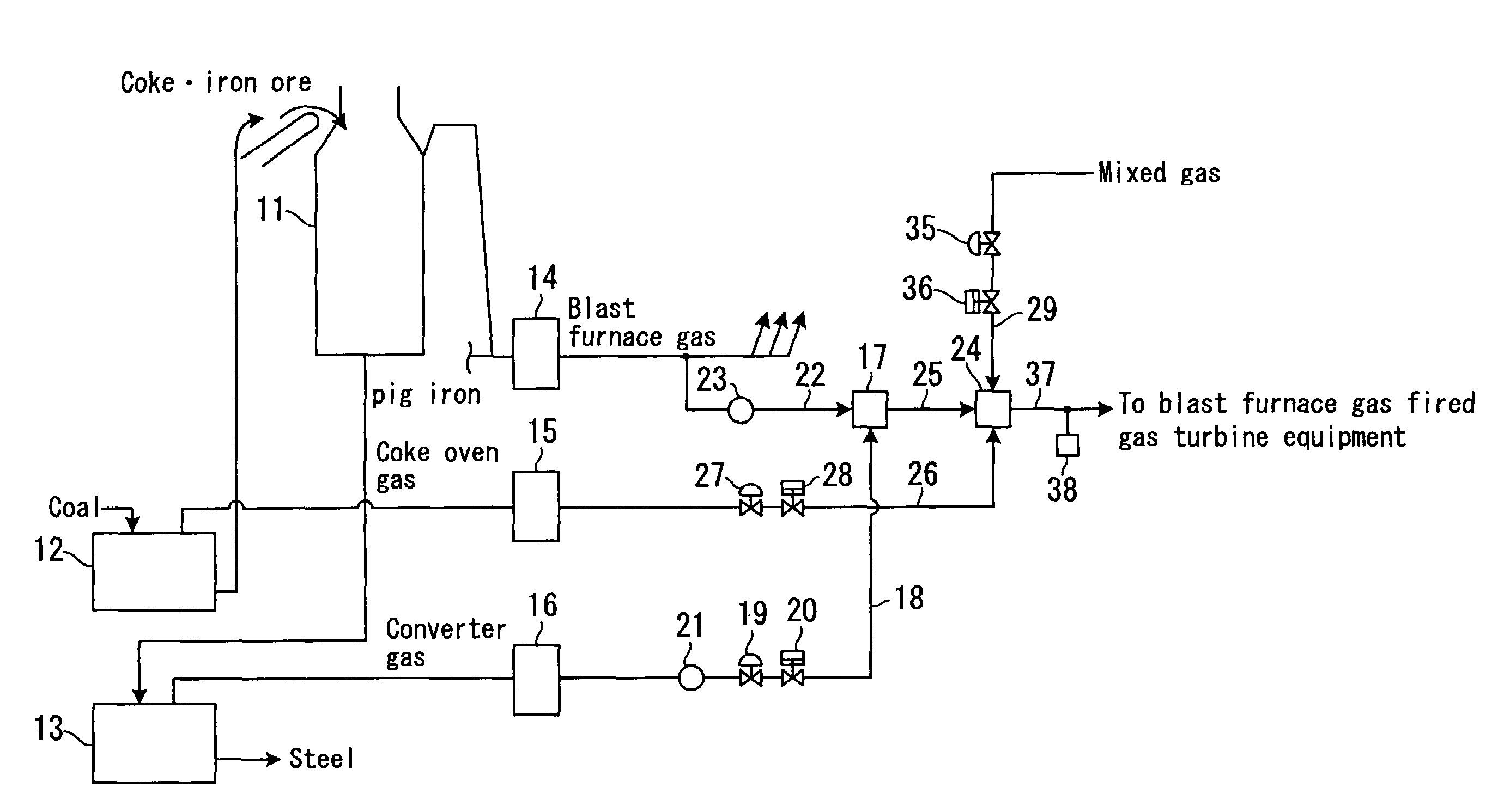
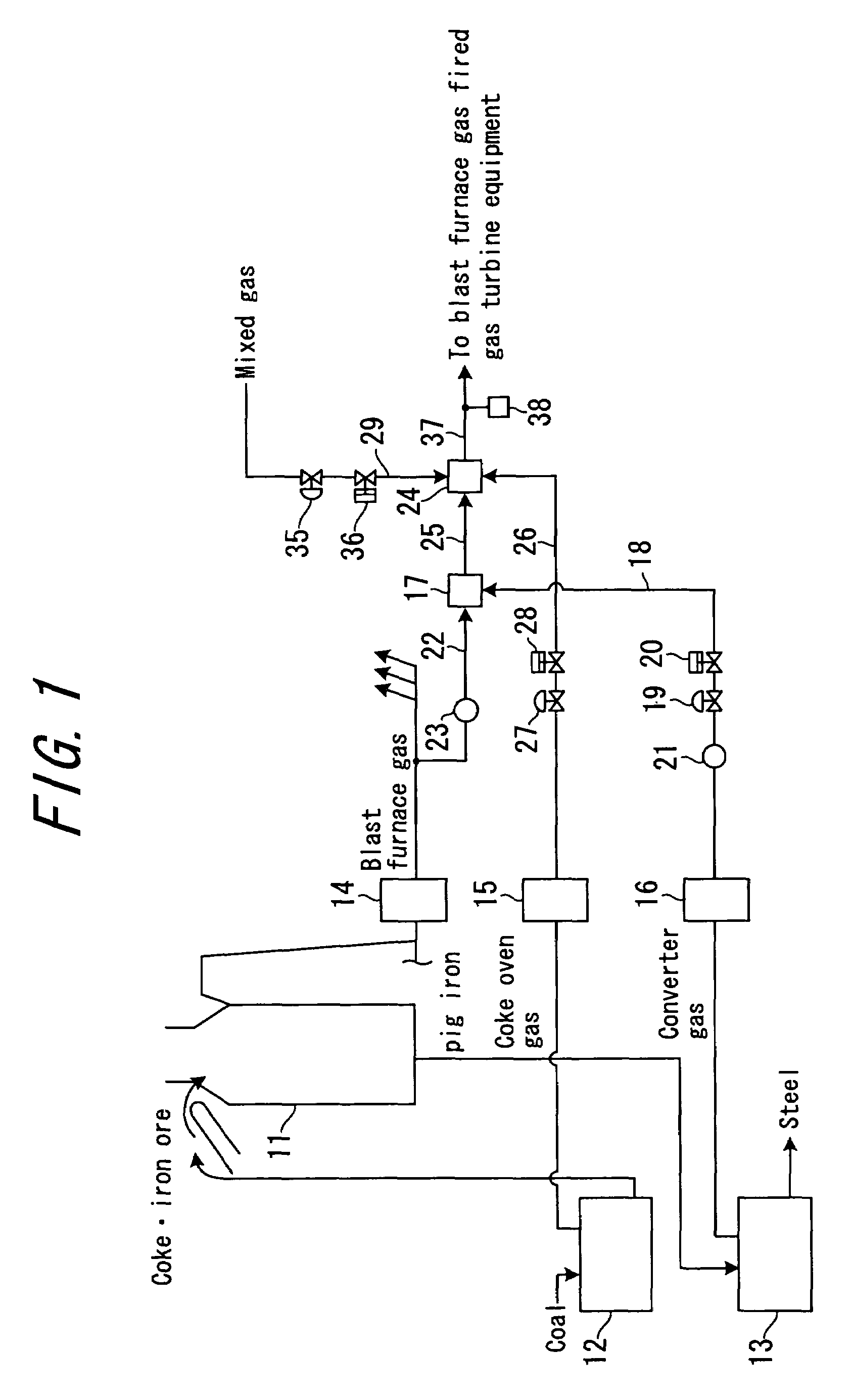
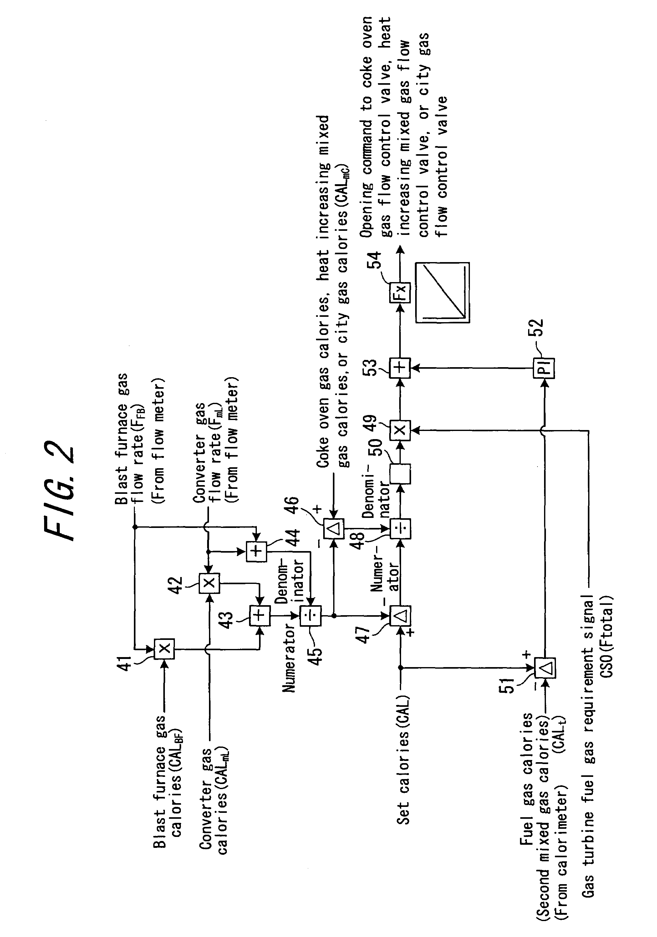
[0085]FIG. 1 is a configurational drawing of a fuel gas production system provided in an iron mill. FIG. 2 is a block diagram showing the circuit configuration of a fuel gas calorie control device according to Embodiment 1 of the present invention applied to the fuel gas production system. FIG. 3 is a graph showing the relationship between a gas turbine consumed fuel gas flow rate and a gas turbine fuel gas requirement signal. FIG. 4 is a graph showing an example of the mixing ratio among a blast furnace gas, a converter gas, and a coke oven gas for producing a fuel gas.

[0086]As shown in FIG. 1, an iron mill is equipped with a blast furnace (smelting furnace) 11, a coke oven 12, and a converter 13. The coke oven 12 is a furnace for producing coke from coal, and a coke oven gas (COGas) is generated in the coke oven 12 during this production. The coke oven gas contains flammable components, such as H2 (55%), CO (7%) and CH4 (20%), N2 and CO2, and its calories are, for example, 4,500 k...

embodiment 2

[0110]FIG. 5 is a configurational drawing of a fuel gas production system provided in an iron mill. FIG. 6 is a block diagram showing the circuit configuration of a fuel gas calorie control device according to Embodiment 2 of the present invention applied to the fuel gas production system. In FIGS. 5 and 6, the same parts as those in FIGS. 1 and 2 are assigned the same numerals as those in FIGS. 1 and 2.

[0111]As shown in FIG. 5, in a fuel gas production system according to the present Embodiment 2, a blast furnace gas calorimeter 61 as a blast furnace gas calorie measuring means for measuring the calories of a blast furnace gas is provided in a blast furnace gas supply piping line 22, a converter gas calorimeter 62 as a first heat increasing gas calorie measuring means for measuring the calories of a converter gas (first heat increasing gas) is provided in a converter gas supply piping line 18, and a coke oven gas calorimeter 63 as a second heat increasing gas calorie measuring mean...


PUM

PropertyMeasurementUnit
gas flow rateaaaaaaaaaa
flow rateaaaaaaaaaa
flow rate ratioaaaaaaaaaa

Abstract

Calories of a first mixed gas are predicted by calculations based on the mixed flow rate of a blast furnace gas and the mixed flow rate of a converter gas measured by flow meters, and preset blast furnace gas calories and converter gas calories; the flow rate ratio of the mixed flow rate of a coke oven gas to a gas turbine consumed fuel gas flow rate is calculated based on the predicted calories, set calories, and preset coke oven gas calories; the mixed flow rate required value of the coke oven gas is calculated based on the flow rate ratio and a gas turbine fuel gas requirement signal corresponding to the gas turbine consumed fuel gas flow rate; and the opening of a coke oven gas flow control valve provided in a fuel gas production system is controlled, based on the mixed flow rate required value, to control the mixed flow rate of the coke oven gas.

Description

BACKGROUND OF THE INVENTION[0001]1. Field of the Invention[0002]This invention relates to a fuel gas calorie control method and device for controlling the calories of a fuel gas (fuel gas produced using a blast furnace gas) which is supplied to blast furnace gas fired gas turbine equipment.[0003]2. Description of the Related Art[0004]An iron mill utilizes a blast furnace gas discharged from a blast furnace as a fuel gas for blast furnace gas fired gas turbine equipment, or utilizes it for other facilities to make the effective use of the blast furnace gas.[0005]A blast furnace gas is a gas which is relatively low in calories, and always causes calorie changes, for example, depending on the operating state of a blast furnace. If a blast furnace gas is utilized as a fuel gas for blast furnace gas fired gas turbine equipment, therefore, a heat increasing gas is mixed with the blast furnace gas in order to produce a fuel gas utilizable for the blast furnace gas fired gas turbine equipme...

Claims


Application Information

Patent Timeline
Patent Type & Authority Patents(United States)
IPC IPC(8): F02C9/26
CPCC10K3/06C10L3/08C21B7/002C21C5/38F27B1/28F27D17/00F27D19/00F27D21/00F27B1/26F23N2021/10F27D2019/0006C21B2100/64F23N2221/10Y02P20/10
Inventor TANABE, HIROSHIYAMASHITA, HIDEKAZU
Owner MITSUBISHI POWER LTD
Why Eureka
Try Eureka