[0060] Thus, calorie control can be exercised by mixing the two types of heat increasing gases (first heat increasing gas, second heat increasing gas) with the blast furnace gas. Even if rapid calorie changes occur in the first mixed gas owing to flow rate changes of the first heat increasing gas, the calorie changes are predicted (predicted calories are calculated), and the flow rate of the second heat increasing gas is advancedly controlled so as to compensate for the calorie changes. Thus, the calories of the fuel gas (second mixed gas) can be kept at the set calories. Furthermore, the calorie changes of the first mixed gas due to the flow rate changes of the first heat increasing gas can be compensated for by the second heat increasing gas. Hence, the mixed flow rate of the first heat increasing gas can be set arbitrarily.
[0066] Thus, calorie control can be exercised by mixing the two types of heat increasing gases (first heat increasing gas, second heat increasing gas) with the blast furnace gas. Even if rapid calorie changes occur in the first mixed gas owing to flow rate changes of the first heat increasing gas, the calorie changes are predicted (predicted calories are calculated), and the flow rate of the second heat increasing gas is advancedly controlled so as to compensate for the calorie changes. Thus, the calories of the fuel gas (second mixed gas) can be kept at the set calories. Furthermore, the calorie changes of the first mixed gas due to the flow rate changes of the first heat increasing gas can be compensated for by the second heat increasing gas. Hence, the mixed flow rate of the first heat increasing gas can be set arbitrarily.
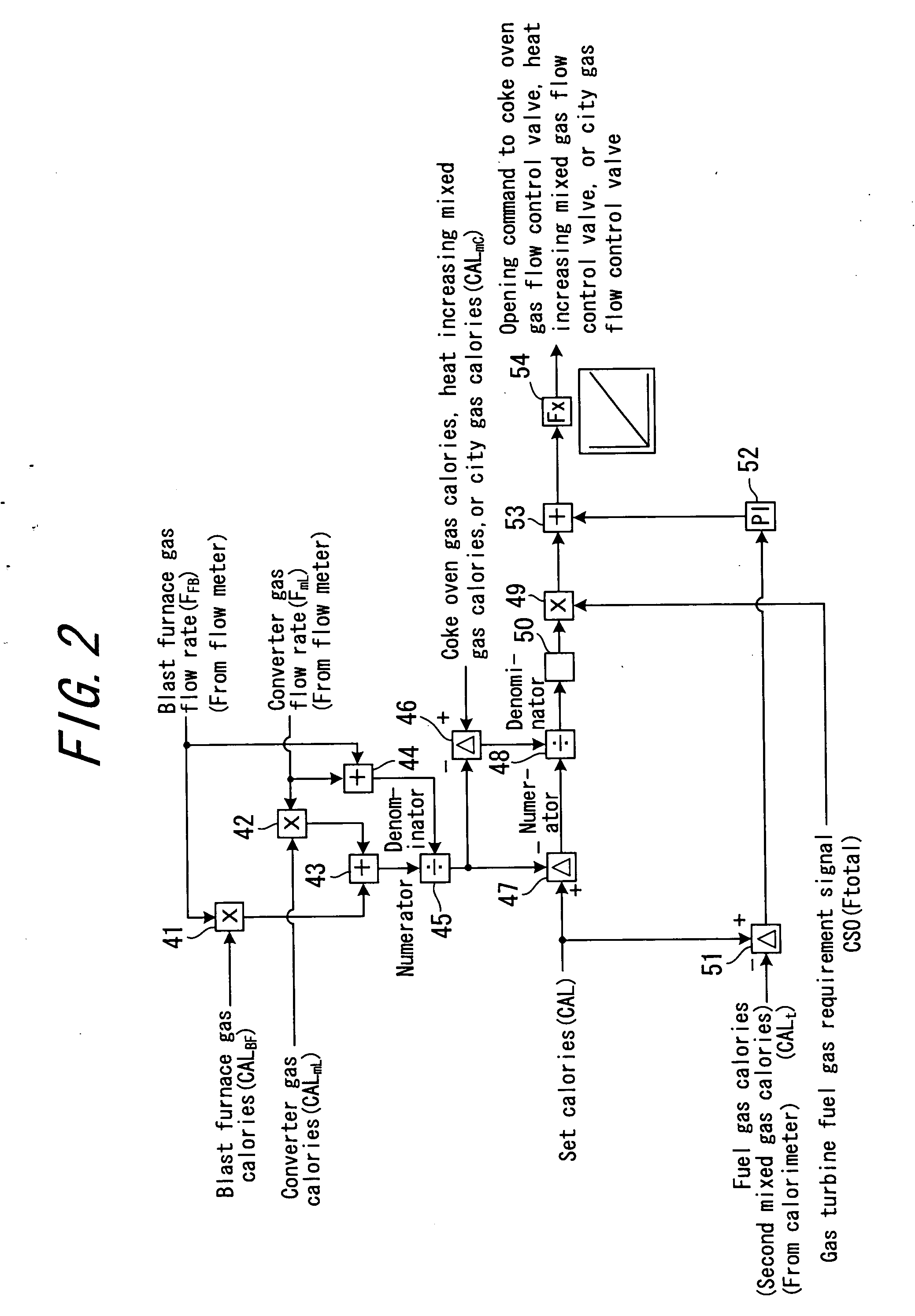
[0067] Furthermore, the blast furnace gas calories measured by the blast furnace gas calorie measuring means, the first heat increasing gas calories measured by the first heat increasing gas calorie measuring means, and the second heat increasing gas calories measured by the second heat increasing gas calorie measuring means are used in calculating the calories of the first mixed gas (i.e., predicted calories), or in calculating the mixed flow rate required value of the second heat increasing gas. Thus, even if the blast furnace gas calories, the first heat increasing gas calories, or the second heat increasing gas calories change, the flow rate of the second heat increasing gas is controlled to keep the calories of the fuel gas (second mixed gas) at the set calories. Hence, calorie changes of the blast furnace gas, the first heat increasing gas, or the second heat increasing gas can be accommodated.
[0069] Thus, the mixing of the second heat increasing gas into the first mixed gas can be performed with a more proper timing, and the calories of the fuel gas (second mixed gas) can be controlled more accurately.
[0071] Thus, even if discrepancy occurs between the calories of the fuel gas (second mixed gas) and the set calories, feedback on the calories of the fuel gas (second mixed gas) measured by the fuel gas calorie measuring means is provided, whereby the flow rate of the second heat increasing gas can be subjected to
feedback control so that the calories of the fuel gas (second mixed gas) agree with the set calories. Thus, the calories of the fuel gas (second mixed gas) can be controlled more accurately.
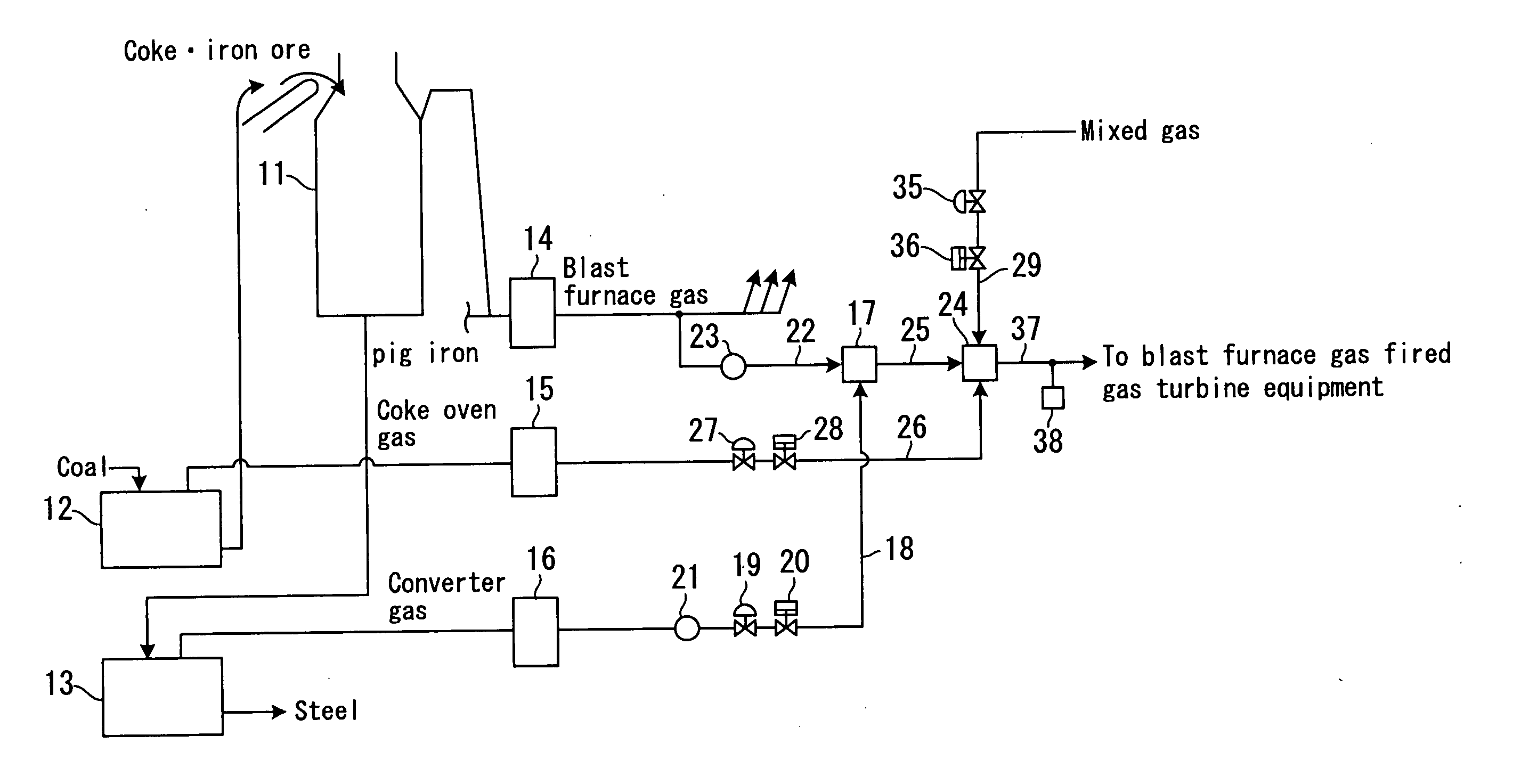
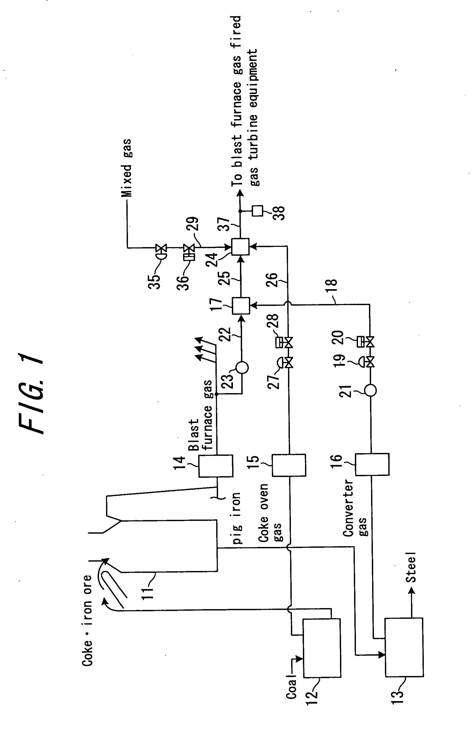
[0073] Thus, calorie control can be exercised even with the use, as the first heat increasing gas, of a gas facing flow rate changes, such as a converter gas discharged from a converter of the iron mill. Even if rapid calorie changes occur in the first mixed gas owing to flow rate changes of the converter gas, the calorie changes are predicted (predicted calories are calculated), and the flow rate of the second heat increasing gas is advancedly controlled so as to compensate for the calorie changes. Thus, the calories of the fuel gas (second mixed gas) can be kept at the set calories. Furthermore, the calorie changes of the first mixed gas due to the flow rate changes of the converter gas can be compensated for by the second heat increasing gas. Hence, the flow rate of the converter gas can be set arbitrarily. Furthermore, the blast furnace gas calories measured by the blast furnace gas calorie measuring means, the converter gas calories measured by the first heat increasing gas calorie measuring means, and the second heat increasing gas calories measured by the second heat increasing gas calorie measuring means are used in calculating the calories of the first mixed gas (i.e., predicted calories), or in calculating the mixed flow rate required value of the second heat increasing gas. Thus, even if the blast furnace gas calories, the converter gas calories, or the second heat increasing gas calories change, the flow rate of the second heat increasing gas is controlled to keep the calories of the fuel gas (second mixed gas) at the set calories. Hence, calorie changes of the blast furnace gas, the converter gas, or the second heat increasing gas can be accommodated.

