
Apparatus, systems and methods for management of raw water and emissions utilizing heat and/or pressure energy within combustion gas sources

a technology of raw water and energy management, applied in the direction of quarries, evaporator regulation/control, separation processes, etc., can solve the problems of inability to mobilely treat flue gasses, scaling and/or plugging of lines, and increasing the problem of fine particles

Inactive Publication Date: 2019-07-04
HORIZON OILFIELD SOLUTIONS
View PDF14 Cites 0 Cited by
  • Summary
  • Abstract
  • Description
  • Claims
  • Application Information

AI Technical Summary

Benefits of technology

This patent describes a system for vaporizing raw water by using engine exhaust gas. The system includes a chamber with a raw water influx system that allows the exhaust gas and water to quickly interact, resulting in the evaporation of water and the concentration of contaminants. The system can be controlled actively or passively, with the air knife being adjusted based on user input or sensed variables such as temperature or pressure. This allows for more predictable gas / water mixing behavior, resulting in a more efficient vaporization process.

Problems solved by technology

While larger particles are generally easily removed, finer particles can become increasingly problematic within the concentrating solutions as viscosity increases and increasingly larger particles may become suspended in the solution and can lead to scaling and / or plugging of lines.
In other words, heretofore there has been no incentive for mobile treatment of flue gasses on remote or stranded drilling sites because there are local and national exemptions to standard air emission regulations on oil and gas drilling sites related to diesel engine exhaust volume and concentration of discharge within relatively short timeframes.
The byproduct of the combustion heat utilized by these systems is a low grade heat that is no longer economically usable by current heat exchange technology and which is vented to atmosphere using large chimney stacks.
As one example a 50 MW Steam Generator may have a 2-3 meter diameter flue stack, downstream of an economizer, which releases flue gas to atmosphere with an approximate temperature of 150° C.-200° C. Drawbacks of prior art systems are an inability to utilize this low grade heat.
Drawbacks to other prior art systems is they have to bring the heat from 30+ meters up a flue stack to ground level for processing, and by doing so lose more heat.
These latter systems although described as compact are not light nor compact enough satellite installation at the top of the flue stack.
Further, even if prior art systems were light and compact, they are prone scale buildup within their systems, requiring ground level operator access for ongoing cleaning and maintenance, which results in ongoing, undesirable operational expense.
As can be seen from Table 1, in many cases as an engine becomes larger it is generally less able to tolerate significant backpressure.
Additionally, as a result of the focus of US '844 on land fill gas waste heat utilization with no or little associated positive pressure, there is no teaching of using the positive pressure within engine exhaust gas to at least partially atomize, shear or break droplets as a means for interfacial surface area generation.
Regarding the latter, a drawback to this system is that new energy input is required, at a cost, in order to shear and mix water with a heat source.
Substantial drawbacks to various US '844 systems are the described requirement for cleaning and maintenance of scale and salt deposits due to many wet / dry surfaces within the system.
These drawbacks are also associated with a cyclonic demister whose inlet is tangential rather than concentric in that within the cyclone there are substantial dry surfaces that buildup scale, salts, etc. and require much maintenance and cleaning.

Method used


Image

  • Apparatus, systems and methods for management of raw water and emissions utilizing heat and/or pressure energy within combustion gas sources
  • Apparatus, systems and methods for management of raw water and emissions utilizing heat and/or pressure energy within combustion gas sources
  • Apparatus, systems and methods for management of raw water and emissions utilizing heat and/or pressure energy within combustion gas sources

Examples


Embodiment Construction

Rationale and Introduction

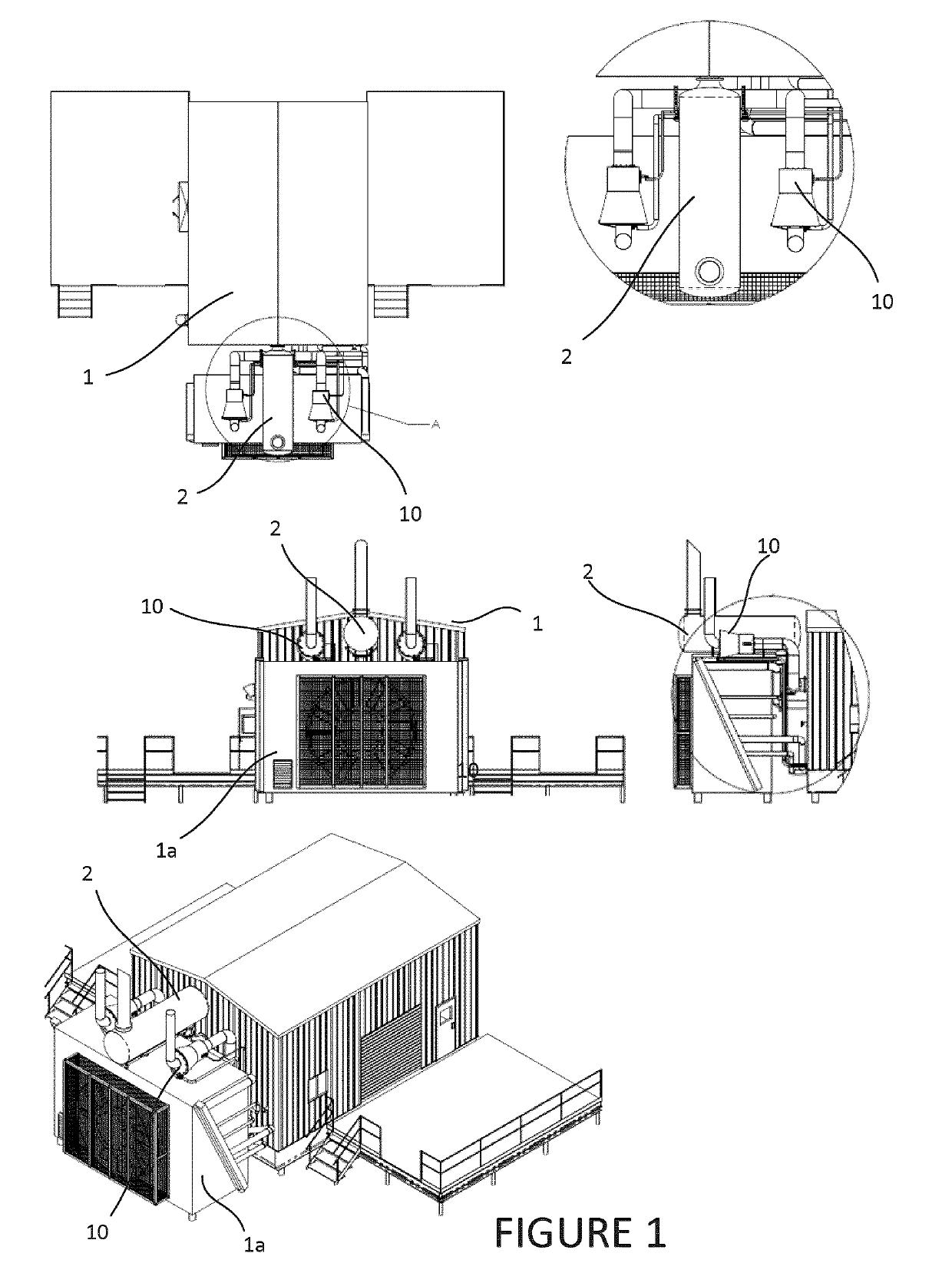
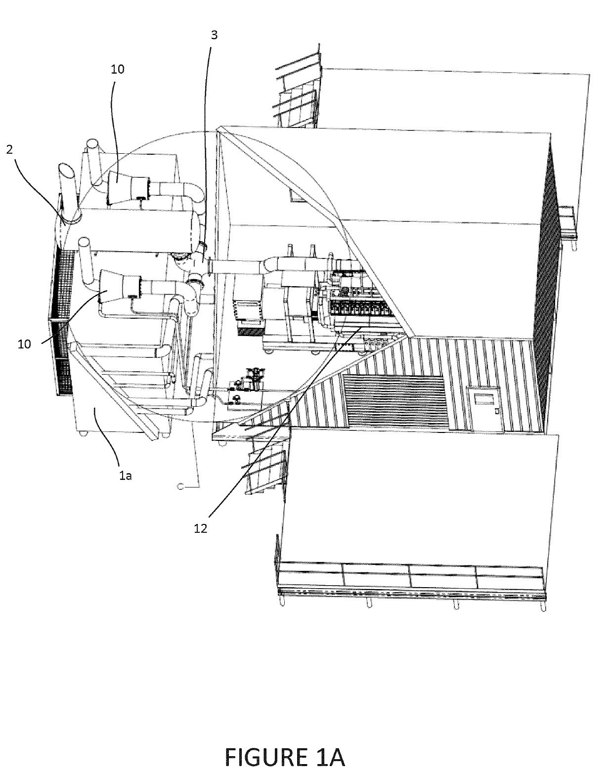
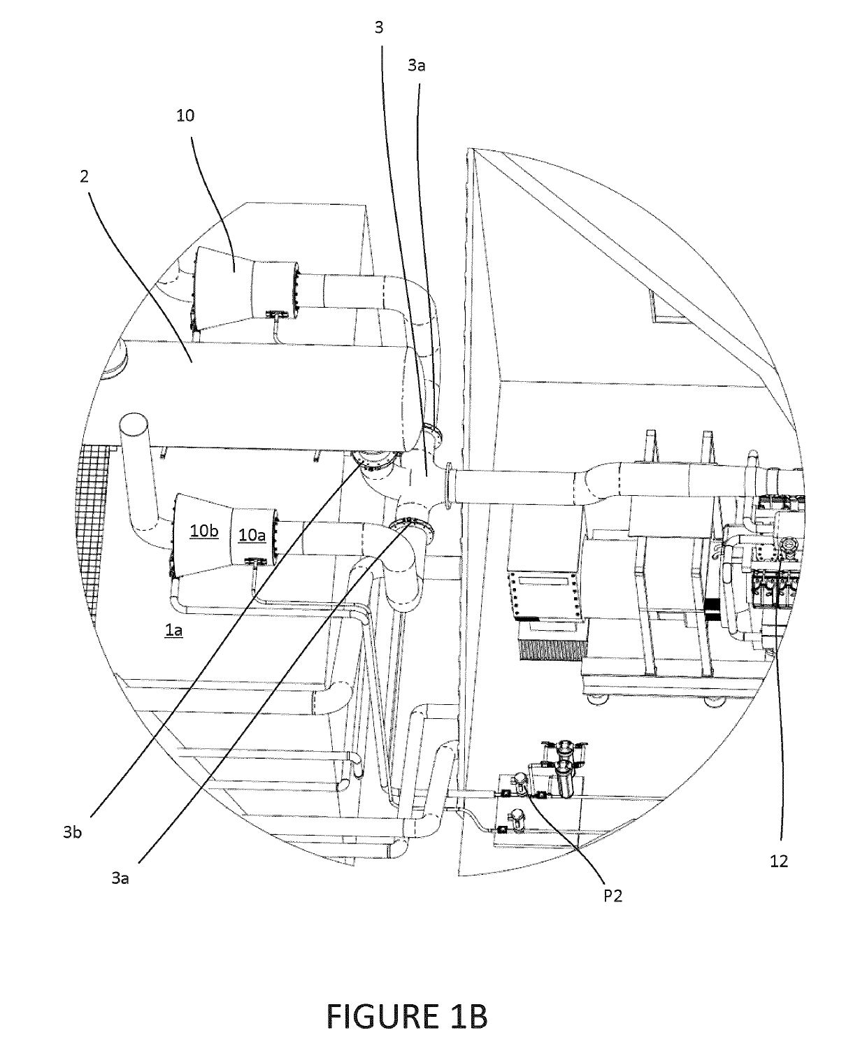
[0184]The subject invention seeks to improve the efficiency of the vaporization of waste water utilizing “waste” heat and pressure from a heat source such as an engine (e.g. an engine / generator combo unit or exhaust from steam generators, turbines, boilers, flares, flame exhaust and the like) so as to effect a reduction of the volume of raw water and the concentration of contaminants within the raw water and / or the exhaust gasses. The invention also provides a low-maintenance solution for water vaporization by reducing the effects of scaling. In addition, the invention provides effective systems and methods to muffle ICE engine noise during water vaporization processes.

[0185]In various embodiments, the invention also seeks to perform one or more of the following:[0186]a. reduce or minimize new energy input over and above the primary heat source from an ICE, combustion gas, flare gas or other similar source;[0187]b. minimize pressure drop related to water va...


PUM

PropertyMeasurementUnit
pressureaaaaaaaaaa
pressureaaaaaaaaaa
sizeaaaaaaaaaa

Abstract

The invention relates to methods, systems and apparatus for distributed management of raw water and internal combustion engine (ICE) gas emissions generated during industrial operations. One aspect of the invention at least partially utilizes a hot gas air knife to increase or partially increase surface area between a raw water and a hot gas in order to vaporize a proportion of the aqueous phase of the raw water and concentrate contaminants within a residual raw water concentrate. The water vapor generated by the vaporization process may be demisted, discharged directly to the atmosphere or alternatively condensed and captured for use. Another aspect relates to how the liquids and gasses interact to continuously flush the surfaces of the system which may help mitigate scaling issues. The invention may help facilitate rapid transfer of ICE combustion gas particulate and ICE combustion gas chemicals onto and into the raw water as it concentrates.

Description

FIELD OF THE INVENTION[0001]The invention relates to methods, systems and apparatus for distributed management of raw water, heat energy within combustion gas and internal combustion engine (ICE) gas heat and pressure generated during industrial operations. Such operations include but are not limited to oilfield drilling, completions and production operations with mobile, semi-permanent and / or permanent processing units. One primary aspect of the invention provides a compact, in-line, all-in-one concentrator, vaporizer, demister, and muffler apparatus. The apparatus can be configured in various embodiments and can provide various advantages to operators seeking to vaporize raw water and / or concentrate contaminants within raw water using waste heat and pressure from such operations including ICE's and other sources. These advantages can include:[0002]a. minimal new energy input over and above a primary heat source such as an ICE, combustion gas, flare gas or other similar source;[000...

Claims


Application Information

Patent Timeline
Patent Type & Authority Applications(United States)
IPC IPC(8): C02F1/16C02F1/12C02F1/04B01D1/00B01D1/14B01D1/16B01D1/30C02F1/00
CPCC02F1/16C02F1/12C02F1/048B01D1/0058B01D1/0082B01D1/14B01D1/16B01D1/305C02F1/008C02F2103/10C02F2209/38C02F2303/22B01D5/006B01D3/346B01D47/06B01D45/16B01D1/30B01D53/92F22D5/00C02F1/10E03B1/041B01D5/0003B01D45/08C02F2101/10C02F2101/301C02F2101/32
Inventor CURLETT, JOSHUAWANLIN, HUGUES
Owner HORIZON OILFIELD SOLUTIONS
Learn More