Omni-directional wind turbine

a wind turbine and rotor blade technology, applied in the direction of electric generator control, renewable energy generation, greenhouse gas reduction, etc., can solve the problems of high stress level on the rotor blades, rotor speed to be extremely high, and the level is far from being achieved at present, so as to reduce air leakage

Active Publication Date: 2008-07-15
KATRU ECO INVENTIONS PTY LTD
View PDF14 Cites 82 Cited by
  • Summary
  • Abstract
  • Description
  • Claims
  • Application Information

AI Technical Summary

Benefits of technology

[0038]Preferably, the omni-directional, shrouded vertical wind turbine wherein focusing of air entering the shroud by the plurality of curved members results in the air gate being formed across air passages formed by inactive members of the plurality of curved members so as to reduce air leakage.
[0090]using the curved members and the vertical support members to focus airflow from the windward side of a central collection chamber substantially directly across the full width of the chamber to a diametrically opposite side of a central collection chamber so as to substantially form an air gate on the opposite and adjacent sides of the chamber to reduce air leakage from the opposite and adjacent sides of the central collection chamber;using the curved members and the vertical support members to direct the airflow to substantially all of the underside of a rotating member;using a hollow member to permit the airflow leaving the rotating member to gradually return to atmospheric pressure levels.
[0091]In a further broad form of the invention there is provided a method for using a hollow member in an omni-directional, shrouded vertical wind turbine for generating electricity comprising the steps:using a wedge and collar arrangement attached to the hollow member so as to reduce free wind interference from a wind ward side of the hollow member;
[0092]using wedge shaped collars attached circumferentially to an external surface of the hollow member so as to concentrate and direct a portion of the free wind to air channels formed through the hollow member and exiting tangentially to an internal surface of the hollow member;using the channels to discharge air from the channels, parallel to a direction of main air flow within the hollow member;wherein back pressure at a throat of the hollow member is decreased and air flow through a rotating member located near the throat of the hollow member is increased;wherein separation of main air flow along the internal surface of the hollow member is reduced so as to permit pressure recovery within the hollow member with reduced pressure energy losses;wherein a suction effect across an outlet of the hollow member is increased.

Problems solved by technology

However, even with today's high-tech machines this level is far from being achieved at present.
Regardless of these advantages, the fact that a large shroud type structure needs to be flexibly mounted in a highly wind exposed position and be rotatable to face the wind has been a major draw back of such devices.
Also, as the free wind speed increases, the magnification through the use of the shroud elevates the rotor speed to extremely high levels with consequent high stress levels on the rotor blades.
The first category offered much promise as it has the capacity for augmentation effects of well over ten fold but as yet these have not met commercial realization.
The main draw backs of these devices have been the significant cost of construction, due to complex shape requirements, high number of moving parts, high cyclic loading on the rotors as they crossed from active segments to inactive segments in their swept area, the leakage losses through inactive sections and the significant energy losses in forcing the free wind to move in a highly constricted manner through the augmenting devices.
The high levels of constrictions generate resistance and energy losses which need to be over come by the free wind utilizing some of its energy.
In many instances these resistances tend to reduce the quantity of wind passing through the device to such low levels that the augmentation could indeed be significantly negative.
Thus even if other benefits were possible; the additional costs of any augmenting device cannot be justified.
As a consequence, augmented vertical-axis machines (even horizontal units) have not been commercially attractive and have not achieved acceptance in competition with the present form of horizontal-axis wind turbines.
However, because of opposition from environmentalists with regard to, injury to migrating bird life as well as prohibition by regulating authorities sighting intolerable low frequency noise, stroboscopic light reflection effects and safety hazards associated with these large propeller machines in populated areas, many areas which would be ideal for generating wind energy, such as atop large buildings, are simply off-limits.
Due to the above these machines, are remotely located significantly away from the area of power usage, thus necessitating construction of expensive power grids to transport the energy produced to the consumers, generally living in large urban areas.
Consequently, there is a further reduction in available power due to losses in the transmission grid and increased costs of transmission.
In addition these machines are also not capable of being located in areas where, high levels of wind resource may be available but which experience frequent change in wind direction due to the local terrain or have periods of highly elevated wind velocities such as cyclones or twisters, as these may easily damage the fully exposed rotor blades.

Method used


Image

  • Omni-directional wind turbine
  • Omni-directional wind turbine
  • Omni-directional wind turbine

Examples


Embodiment Construction

General

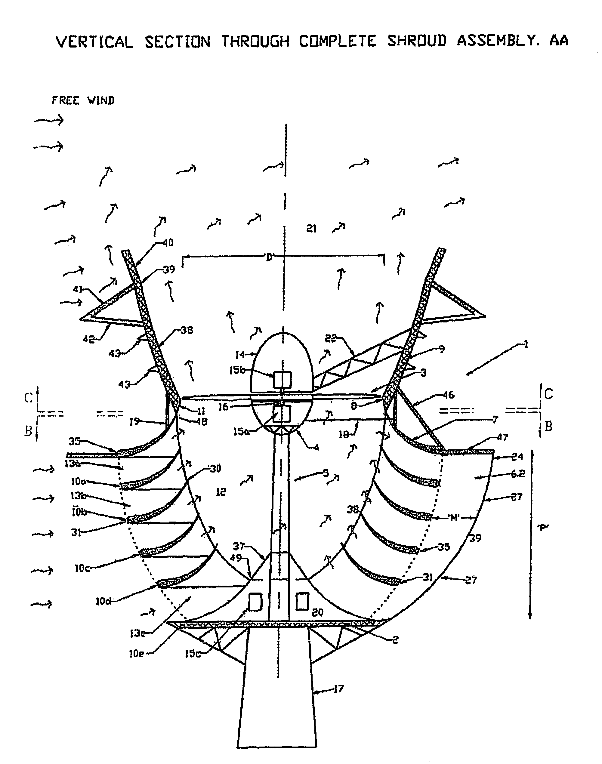
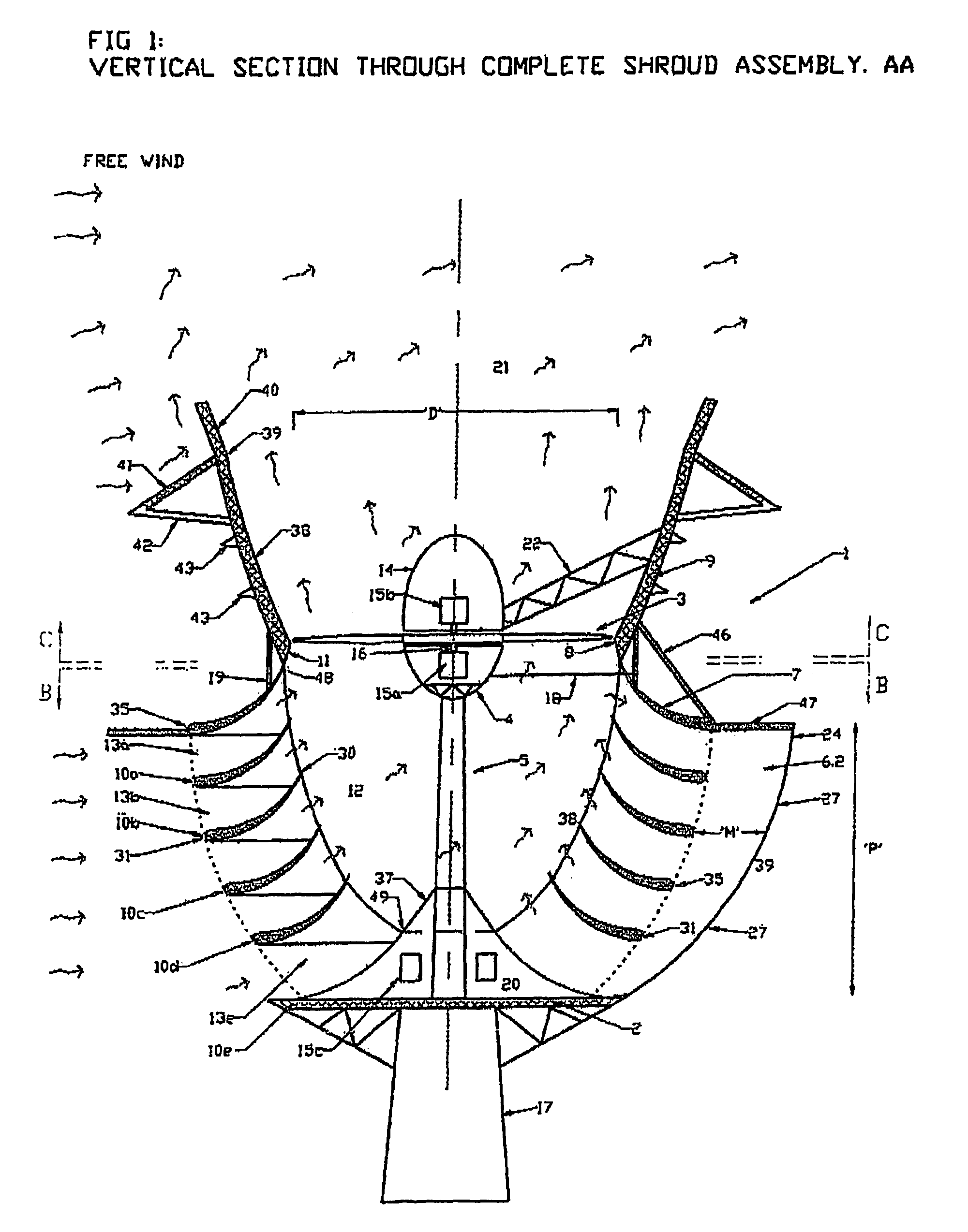
[0102]1 shows an embodiment of the present invention. An omni-directional augmented wind turbine assembly 1 is mounted with its base 2 rigidly connected to a support column 17.

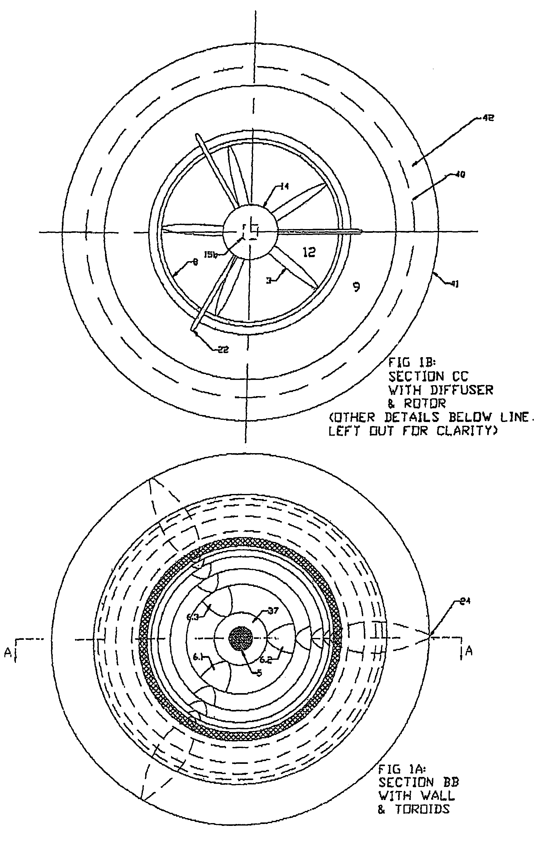
[0103]The turbine rotor 3 of diameter ‘D’ with air foil rotor blades is attached via a central rotating shaft 16 to equipment within the non rotating hub 4 which is supported by a column 5 extending from the base 2 of the complete assembly. The rotor 3 is a horizontal axis type mounted vertically.

[0104]The hub 4 is retained by additional stay cables 18 attached to the shroud diffuser and supporting wall 19. The hub contains the electrical power generator 15a and all associated gear box and control mechanisms for converting the rotor's torque into electrical power. The void area 20 under the last toroid 10e can be utilized to house other electrical gear 15c required for optimizing the electrical power being supplied to the end user. A ladder to access the hub is provided through the column 5 from the bas...


PUM


Abstract

An omni directional, vertical discharge wind turbine, consisting of a shroud that captures wind from any direction and directs it to flow vertically through a throat section where an aerofoil multi-bladed rotor is mounted. The rotor shaft is connected to an electrical power generator. The intake of the shroud incorporates multiple horizontally curved blades of toroidal form varying up to nearly twice the size of the rotor diameter, stacked, staggered and secured in place by multiple aerodynamic vertical walls in the radial direction, to form a central collection chamber for wind. The blade curving angles and the stacking arrangement are such that while accelerating and focusing the wind, across the full swept area of the rotor blades, the loss of air from the central collection chamber is significantly reduced by air flow forming a fluid dynamic gate across inactive faces. Utilizing a wedge and collar near the open top discharge the free wind stream flowing across the open top assists in increasing the flow of air through the rotor. With the increased extraction and wider operational envelop, the energy produced per annum of this omni-directional shrouded vertical wind turbine is anticipated to be much higher than that of a standard free wind turbine of same rotor diameter.

Description

CROSS-REFERENCE TO RELATED APPLICATIONS[0001]The present application is a continuation of PCT / AU2005 / 001882 filed on Dec. 14, 2005, which claims priority to an Australian provisional application no AU2004907279 on Dec. 23, 2004.STATEMENT RE: FEDERALLY SPONSORED RESEARCH / DEVELOPMENT[0002]Not ApplicableBACKGROUND[0003]This invention relates to a shrouded omni-directional wind turbine which discharges vertically and is capable of extracting higher quantities of electric power than a free wind turbine of equal diameter.[0004]The exponentially rising global demand for electric power and the significant and entrenched damage caused to the ecosystem through the generation of such power utilizing non-renewable fuels such as oil and coal, together with the rapid depletion of these resources and the lack of other natural resources to keep up with growing demand, has in the recent past provided new impetus to look towards the further development of renewable energy sources.[0005]Mankind has at...

Claims


Application Information

Patent Timeline
Patent Type & Authority Patents(United States)
IPC IPC(8): F03D9/00
CPCF03D1/04F03D3/0427F05B2240/131Y02E10/74F05B2240/30Y02E10/721F05B2240/133F03D80/80F03D9/25Y02E10/72F05B2240/211
Inventor SURESHAN, VAHEISVARAN
Owner KATRU ECO INVENTIONS PTY LTD
Why Eureka
Try Eureka