Differential receiver with wide input common mode range and low duty cycle distortion

a receiver and common mode technology, applied in the field of data transmission, can solve the problems of severe duty cycle distortion in single-ended signal output, affecting the output duty cycle, and the limit of the common mode voltage that the practical sense amplifier can accept, so as to avoid excessive duty cycle distortion, improve the speed, and increase the operating frequency of the signal path

Active Publication Date: 2008-07-15
TAIWAN SEMICON MFG CO LTD
View PDF11 Cites 50 Cited by
  • Summary
  • Abstract
  • Description
  • Claims
  • Application Information

AI Technical Summary

Benefits of technology

[0016]In one embodiment, the output stage may include a first comparator circuit, which may be coupled for receiving the common mode voltage and one of the pair of complementary signals from the intermediate stage. The first comparator circuit may be configured for generating the single-ended output signal. For example, by receiving the common mode voltage, the first comparator circuit may be configured for ensuring that an output duty cycle of the single-ended output signal is substantially equal to a duty cycle of the pair of complementary signals generated in the intermediate stage. By preserving the input duty cycle, the output stage is able to maintain timing margins that could have been degraded by duty cycle distortion in the signal path. The output stage also functions to avoid excessive duty cycle distortion, which could render a down-s...

Problems solved by technology

However, as with most circuits, a practical sense amplifier has a limit as to the common mode voltage that it can accept.
Such large variations in input common mode voltage tend to produce seve...

Method used


Image

  • Differential receiver with wide input common mode range and low duty cycle distortion
  • Differential receiver with wide input common mode range and low duty cycle distortion
  • Differential receiver with wide input common mode range and low duty cycle distortion

Examples


Embodiment Construction

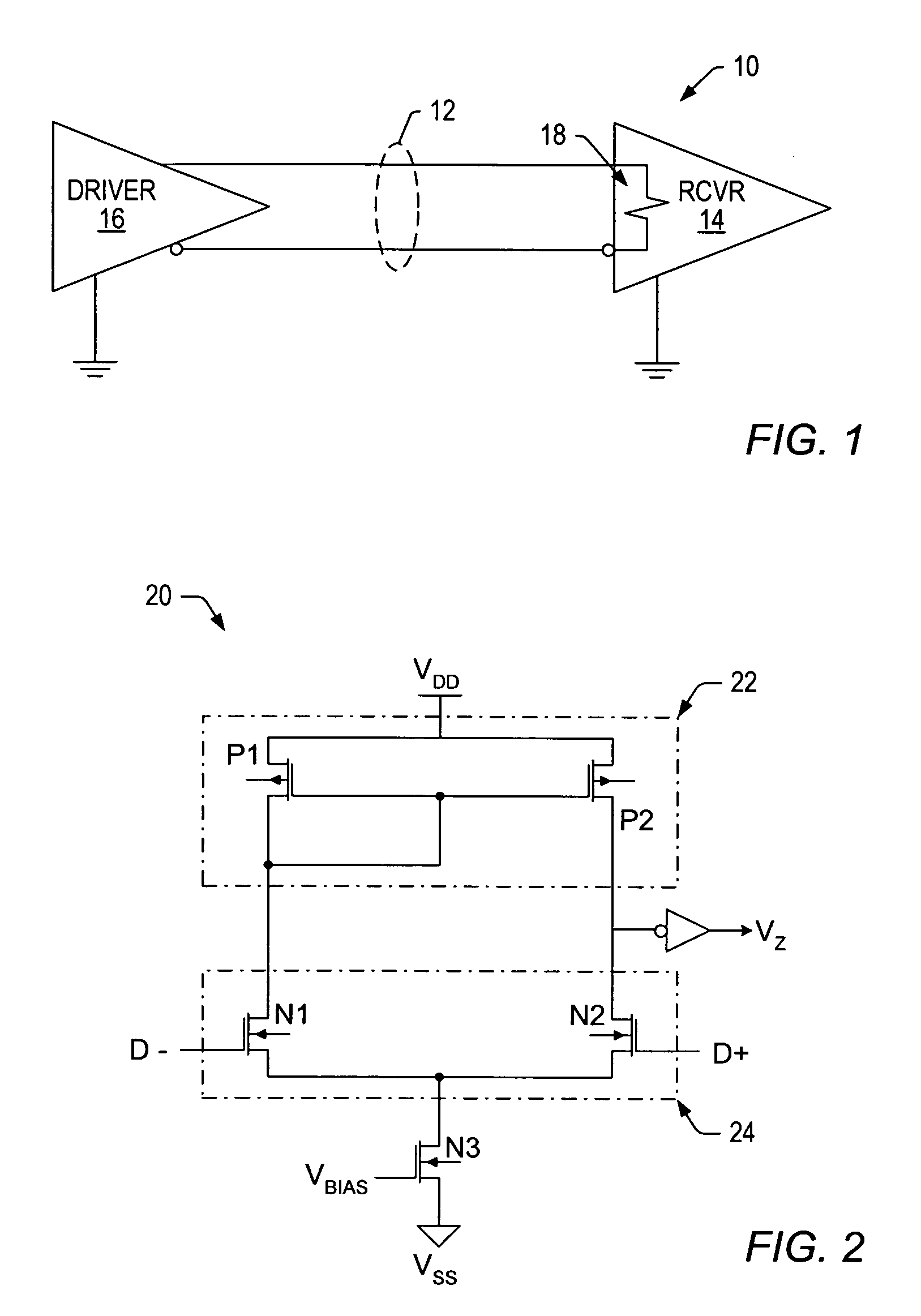
[0033]Turning now to the drawings, FIG. 1 illustrates a transmission system 10. System 10 includes a transmission path made up of possibly two lines that are configured to receive differential signals. The opposing ends of transmission path 12 include a pair of interface devices, or transceivers. Though each interface device preferably includes both a receiver and transmitter, transmission system 10 is shown only with the receiver and transmitter (or driver) portions 14 and 16, respectively. Transmitter 16 drives the differential signals across path 12 and receiver 14 senses the voltage differential between those signals.

[0034]In general, transmission system 10 may involve any communication system that operates in a low voltage environment and conveys data using differential signaling. If the differential signals are low voltage differential signals (LVDS) specified by the American National Standards Institute (ANSI) / Telecommunications Industry Association (TIA) / Electronic Industrie...


PUM


Abstract

A transmission system, circuit and method are provided herein for converting differential signals into low duty cycle distortion, single-ended signals that are insensitive to variations in PVT and input common mode voltage. In one embodiment, the signal translation circuit includes an input stage for receiving a pair of differential input signals and producing one or more differential output signals; an intermediate stage for combining the one or more differential output signals into a pair of complementary signals from which a common mode voltage is detected; and an output stage for generating a single-ended output signal that switches from a first value to an opposite value when one of the complementary signals is substantially equal to the common mode voltage.

Description

PRIORITY APPLICATION[0001]This application claims priority to Provisional Application No. 60 / 504,185 entitled “Differential Receiver with Wide Input Common Mode Range and Low Duty Cycle Distortion,” filed Sep. 19, 2003.BACKGROUND OF THE INVENTION[0002]1. Field of the Invention[0003]This invention relates to the transmission of data and, more particularly, to receivers capable of receiving differential input signals and generating low duty cycle distortion, single-ended output signals regardless of variations in PVT (process, voltage and temperature) and input common mode voltage.[0004]2. Description of the Related Art[0005]The following descriptions and examples are not admitted to be prior art by virtue of their inclusion within this section.[0006]The transmission of data involves sending and receiving data over a transmission path, which is connected between a pair of transceivers. Each transceiver can have a receiver and a transmitter (or driver). In this manner, the receiver fun...

Claims


Application Information

Patent Timeline
IPC IPC(8): H03K19/094H03K19/0175
CPCH03K19/018521H03K19/00384
Inventor KWONG, DAVID K.CHIEN, KUO-CHI
Owner TAIWAN SEMICON MFG CO LTD
Why Eureka
Try Eureka