Method and system for detecting transmitter errors

a transmitter error and detection method technology, applied in the field of data transmission systems, can solve the problems of catastrophic impact on the entire data transmission system, complicated implementation, etc., and achieve the effects of reducing the number of gates, and increasing the frequency of operation

Active Publication Date: 2008-07-15
EMC IP HLDG CO LLC
View PDF4 Cites 3 Cited by
  • Summary
  • Abstract
  • Description
  • Claims
  • Application Information

AI Technical Summary

Benefits of technology

[0010]The present invention is directed to a data transmission system having low latency and increased frequency of operation while having a reduced number of gates in the data transmission system and a reduced number of handshake signals.

Problems solved by technology

The number of handshake signals is directly proportional to the design complexity and verification time of the data transmission system.
Typically, transmitters do not have error recovery mechanisms because their implementation can tend to be complicated.
The transmitter's sudden failure might cause an unpredictable behavior on the receiver side, which in turn could have a catastrophic impact on the entire data transmission system.

Method used


Image

  • Method and system for detecting transmitter errors
  • Method and system for detecting transmitter errors
  • Method and system for detecting transmitter errors

Examples


Embodiment Construction

[0021]As shown in FIG. 3, the data transmission system 10 according to the invention includes a transmitter 12 coupled to a receiver 14 via a data bus 16. The data transmission system 10 operates to transmit data between a data source and a data destination. The data source and data destination may be any devices between which data is transmitted. In one embodiment of the invention, the data source is a PCI Express module which transmits data to a number of data destinations or clients.

[0022]Transmitter 12 includes a number N of transmission devices T0-TN, each of which receive a data bit D[0]-D[N], respectively, for transmission from a data source (not shown) to the receiver 14. In one embodiment of the invention, the number N is 72, i.e. bits 0-71. It will be understood, however, that the selection of the number N depends on the transmission requirements of the system and therefore, any number N may be utilized. Transmitter 12 also includes a request signal transmission register T...


PUM


Abstract

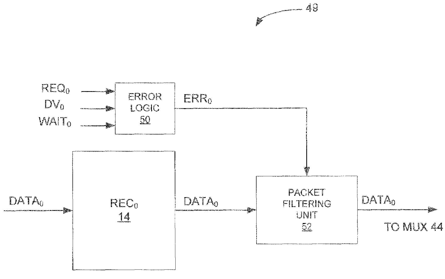
A system for detecting transmission errors in a data transmission system includes a receiver for receiving a data packet transmitted thereto by a corresponding transmitter and transmitting the data packet to a destination device and an error detection device for receiving a plurality of protocol signals that control the operation of the transmitter and the receiver. The error detection device applies at least one predetermined rule to the protocol signals, wherein a violation of the at least one rule by the protocol signals indicates that an error in the transmission of the packet has occurred, and asserts an error signal when the at least one rule has been violated by the protocol signals. The system further includes a packet filtering device coupled to receive the error signal from the error detection device and the data packet from the receiver, wherein, upon receiving the asserted error signal, the packet filtering device terminates the transmission of the data packet to the destination device.

Description

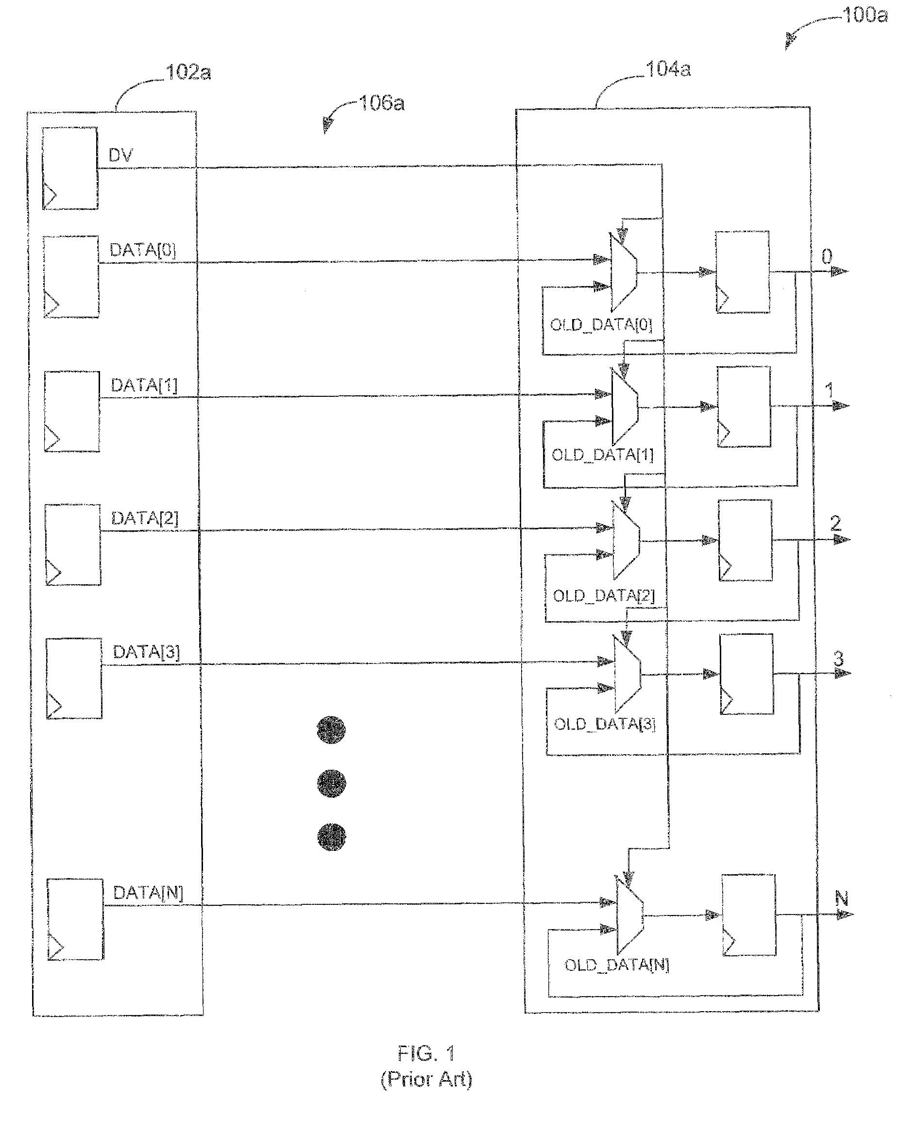
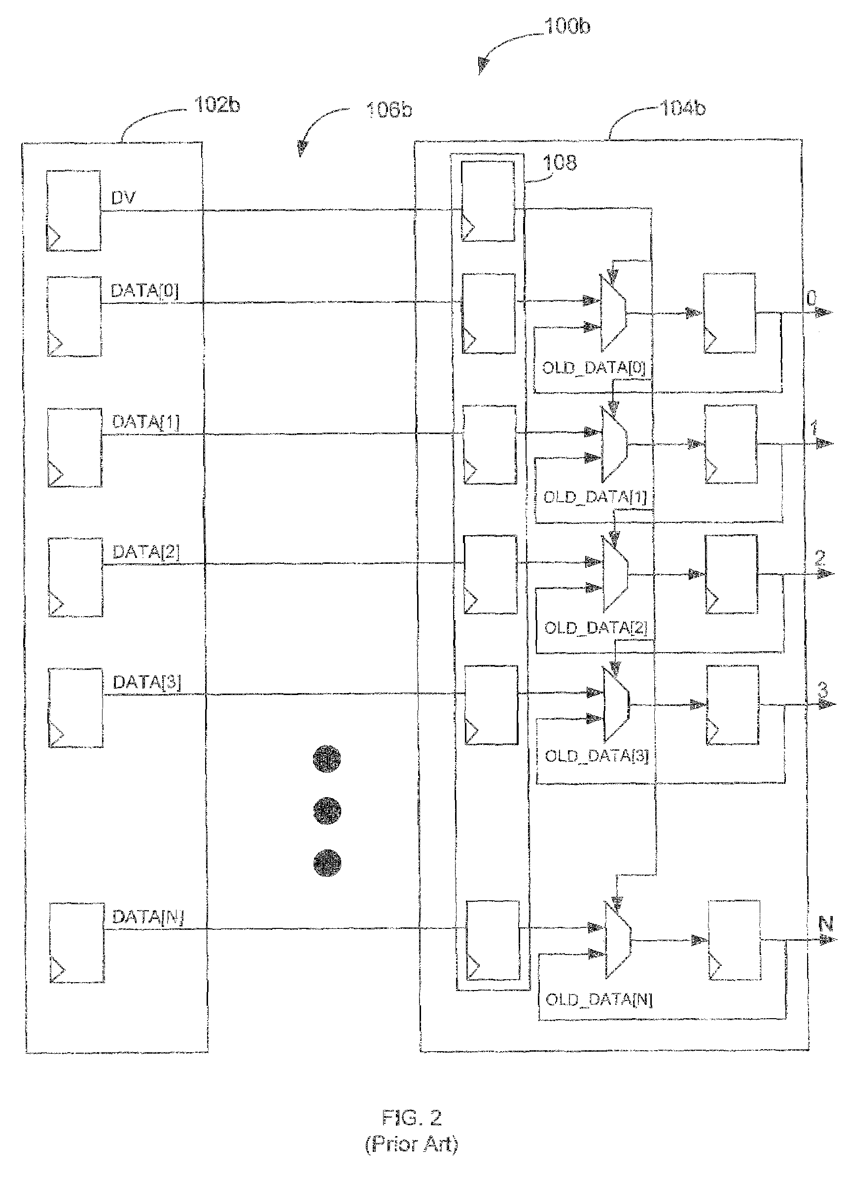
FIELD OF THE INVENTION[0001]The present invention is directed generally to a data transmission system and, more particularly, to a data transmission system having improved latency with a reduced gate count and minimal number of handshake signals.BACKGROUND OF THE INVENTION[0002]A prior art data transmission system 100a as shown in FIG. 1 includes a transmitter 102a for transmitting data to a receiver 104a over a data bus 106a. When data DATA[0]-DATA[N] is to be transmitted from the transmitter 102a to the receiver 104a, the transmitter 102a sends, along with the data, a data valid signal DV to notify the receiver that it is transmitting new data. The receiver 104a samples the data on the data bus 106a when the DV signal is asserted by the transmitter.[0003]The frequency determining delay between the registers of the transmitter 102a and the registers of the receiver 104a is determined by the wire delay of the DV signal plus the fan-out delay of the DV signal feeding all of the multi...

Claims


Application Information

Patent Timeline
Patent Type & Authority Patents(United States)
IPC IPC(8): H04L15/16H04J3/16
CPCH04L1/0045H04L2001/0094
Inventor DAVIS, ALMIRKINNE, JEFFREY S.MACLELLAN, CHRISTOPHER S.SCARINGELLA, STEPHEN L.
Owner EMC IP HLDG CO LLC
Why Eureka
Try Eureka