Speed control method for vehicle approaching and traveling on a curve

a technology of speed control and curve, which is applied in the direction of process and machine control, instruments, navigation instruments, etc., can solve the problems of operator mismanagement of curve, rigid one-size-fits-all models that do not enable modifications, and difficulty for an operator to safely maneuver around a curve, etc., to achieve optimal curve speed and facilitate automatic curve speed control

Active Publication Date: 2008-07-15
GM GLOBAL TECH OPERATIONS LLC
View PDF5 Cites 81 Cited by
  • Summary
  • Abstract
  • Description
  • Claims
  • Application Information

AI Technical Summary

Benefits of technology

[0009]Responsive to these and other concerns caused by conventional curve speed control systems, the present invention concerns an improved curve speed control system that utilizes refining factors to improve operator curve management. Among other things, the system reduces the vehicle speed when approaching a curve if necessary, which will eliminate excessive braking by the operator on the curve and thereby reduces steering effort and the risk of accident. The inventive system is also smart enough to accelerate toward the end of the curve so that cornering performance is improved.
[0012]It will be understood and appreciated that the present invention provides a number of advantages over the prior art, including, for example, providing a more flexible user-specified system. The system is configured to achieve an optimal curve speed following based on accurate road sensing capability, desired speed computation, and control strategy. The system is communicatively coupled to the vehicle, so as to continuously receive sensory feedback, and facilitate automatic curve speed control by the vehicle.

Problems solved by technology

Particularly with respect to automobiles, operator mismanagement of a curve is one of the most prevalent factors contributing to accidents.
Thus, when a vehicle is speeding and friction is insufficient, it is often difficult for an operator to safely maneuver around a curve.
These conventional systems, however, are rigid one-size-fits-all models that do not enable modifications due to operator preference or vehicle characteristics.
These systems also do not provide means for properly addressing special conditions that may modify an allowable curve speed profile where desired.
Of yet further concern, these systems do not accommodate an instantaneous change in curvature radius that may occur at a circular curve termination point, nor provide feedback to enable the optimization of performance, and therefore may result in errors or rapid acceleration when exiting a curve.

Method used


Image

  • Speed control method for vehicle approaching and traveling on a curve
  • Speed control method for vehicle approaching and traveling on a curve
  • Speed control method for vehicle approaching and traveling on a curve

Examples


Embodiment Construction

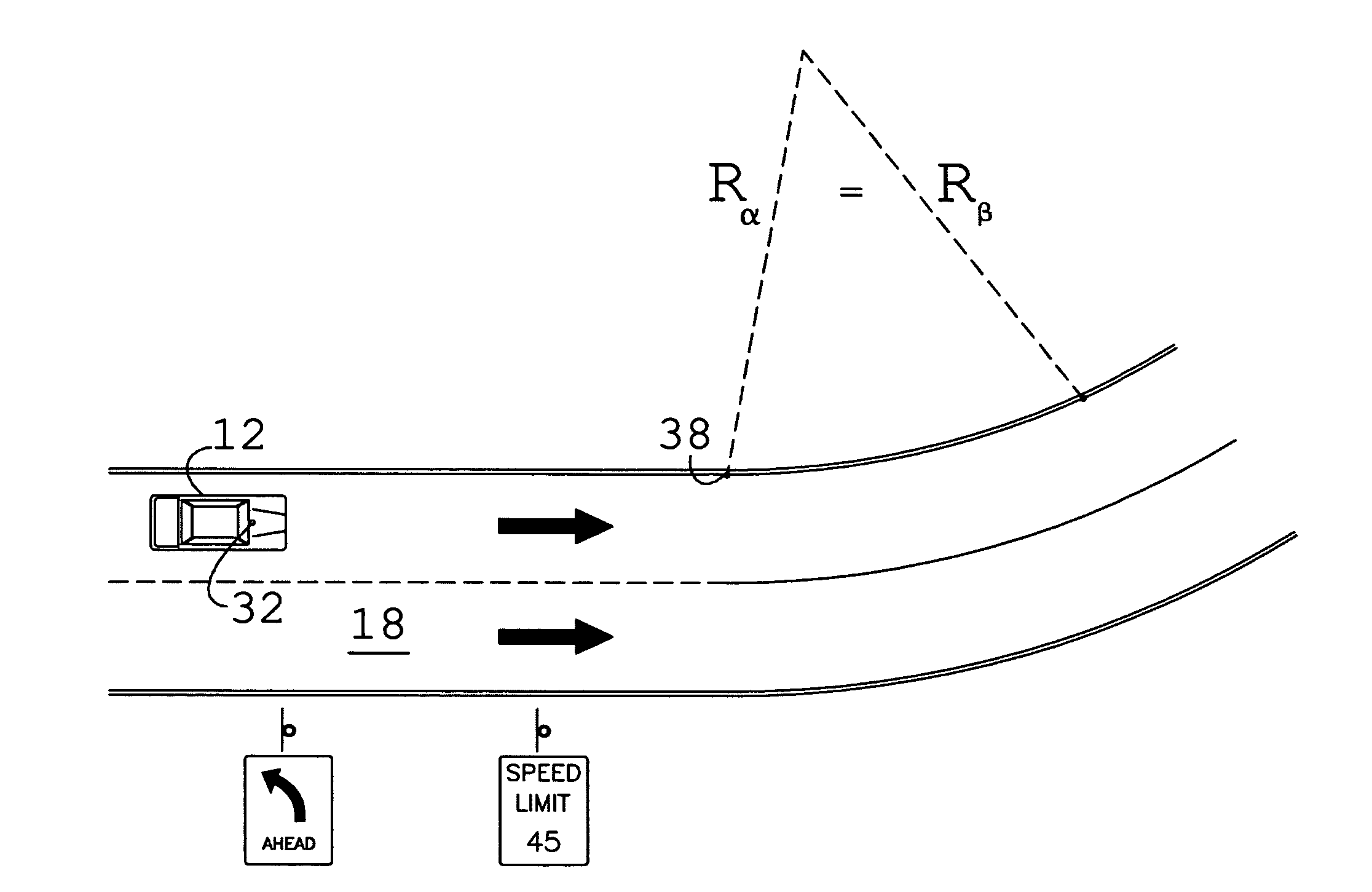
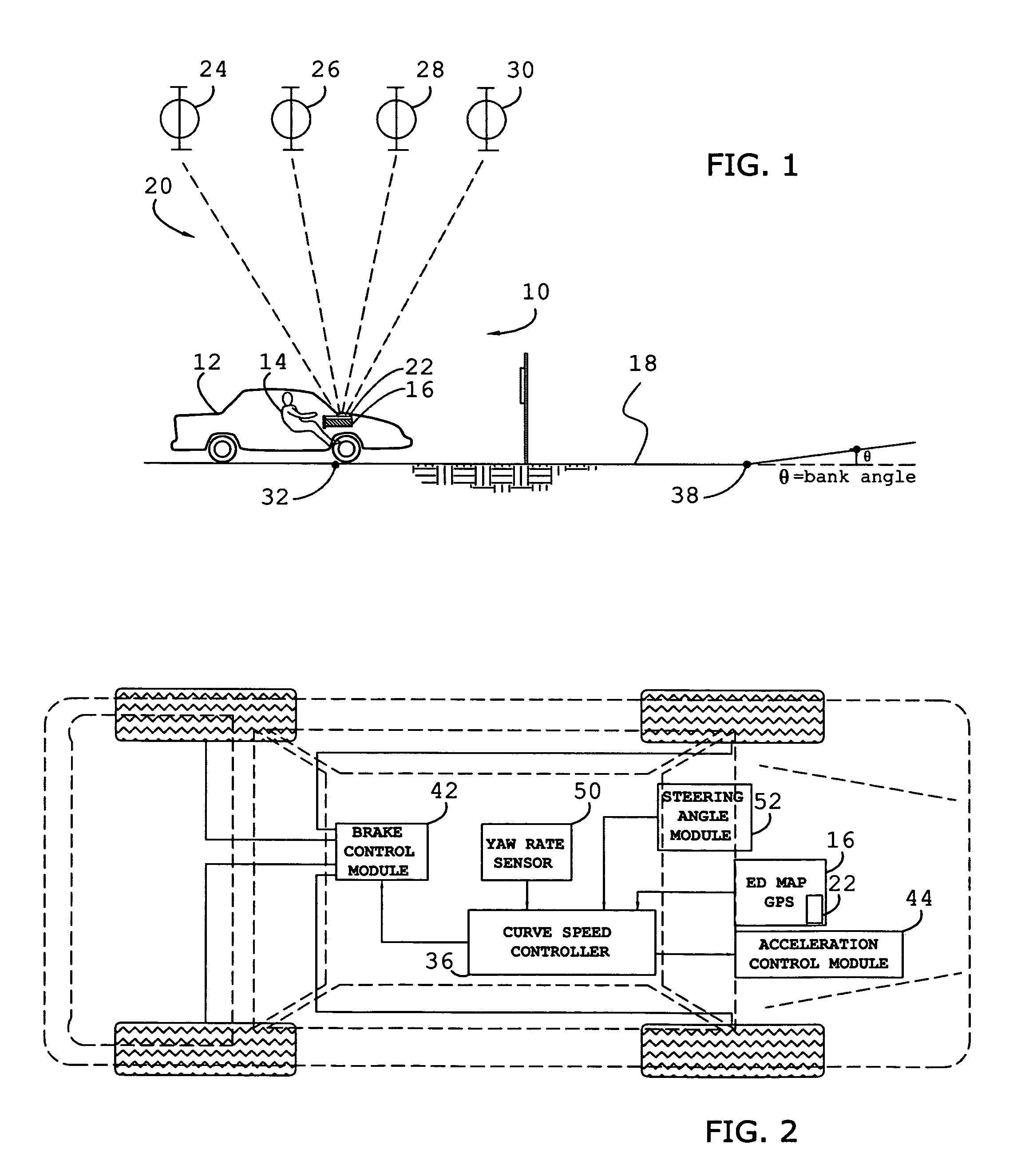
[0024]As shown in FIG. 1, the present invention concerns an improved curve speed control system 10 adapted for use with a vehicle 12 and by an operator 14. The system 10 is configured to identify a plurality of curve points (i.e., nodes), each preferably equidistance from the edge of pavement, of an approaching curve. As further described herein, the system 10 is configured to determine an allowable (i.e., critical or maximum range) curve speed profile, determine a vehicle condition, such as yaw rate, speed and geographic location, and determine a desired curve speed profile based on the allowable curve speed profile and an operator preference or vehicle characteristic input. The system 10 is illustrated and described herein with respect to vehicles such as cars, SUV's, trucks, etc. However, it may also be utilized with airborne and watercraft machines, or whenever navigation and curve management are desired.

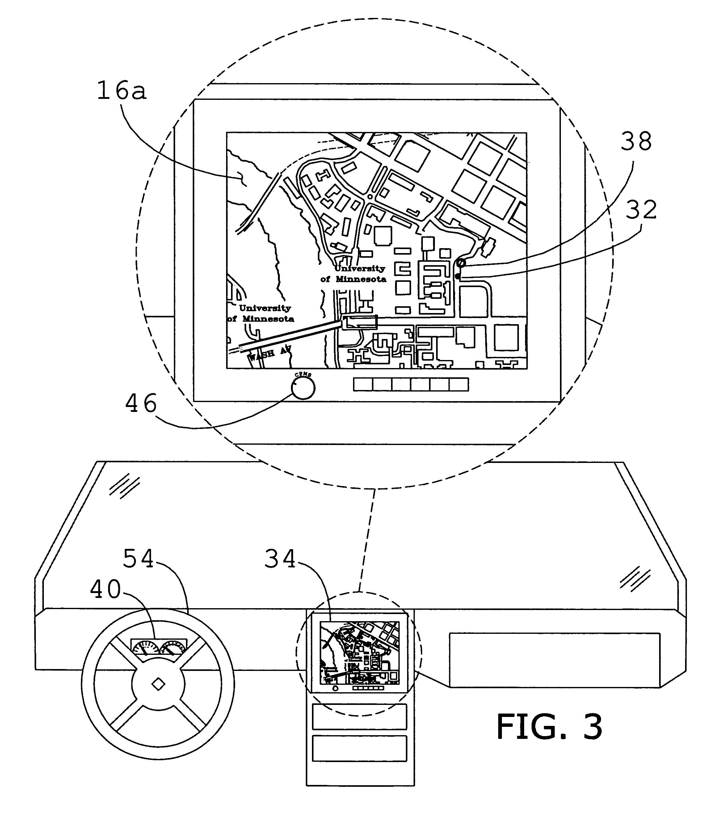
[0025]A preferred embodiment of the system 10 includes a database 16 having...


PUM


Abstract

A vehicle curve speed control system (10) adapted for use with a vehicle (12) having an operator (14), includes a map database (16) representing a current vehicle path, and a locator device (20) communicatively coupled to the database (16) and configured to determine the location of the vehicle (12) on the path. The system (10) further includes a controller (36) configured to identify approaching curve points of a curve (18a) in terms of curvature or radius, and determine a desired speed profile based on operator preference and / or vehicle characteristic input. An acceleration profile is determined, based on the current vehicle speed, and desired speed profile. An acceleration / deceleration command at the present control loop is modified towards achieving an optimal curve speed, and is delivered to either a brake or acceleration module (40,42) to automatically accelerate or decelerate the vehicle (12) accordingly.

Description

BACKGROUND OF THE INVENTION[0001]1. Technical Field[0002]The present invention relates to curve speed control systems, and more particularly to a speed control system configured to facilitate proper operator management of the curve by accelerating or decelerating the vehicle automatically.[0003]2. Background Art[0004]Particularly with respect to automobiles, operator mismanagement of a curve is one of the most prevalent factors contributing to accidents. In these accidents, it is appreciated that excessive lateral forces result when the rate of speed of the vehicle exceeds the rate of speed at which the vehicle could safely or comfortably manage the curve. It is further appreciated that when approaching a curve at excessive speeds the operator typically begins a precarious cycle of excessive braking and steering to resolve the cornering difficulties.[0005]Historically, licensed civil engineers have designed thoroughfare curves by selecting one of a plurality of curve templates, i.e....

Claims


Application Information

Patent Timeline
Patent Type & Authority Patents(United States)
IPC IPC(8): B60T8/24B60T8/58G01C21/30
CPCB60K31/0066B60K31/0083B60W10/184B60W10/06B60W2550/143B60W2552/20B60W2552/30B60W2540/18
Inventor LEE, YONG H.DENG, WEIWEN
Owner GM GLOBAL TECH OPERATIONS LLC
Why Eureka
Try Eureka