Image display device, image display method, and image display program

a technology of image display and image display method, which is applied in the direction of color television details, television systems, instruments, etc., can solve the problems of difficult to improve picture quality, high color saturation level of r colored optical images, and light beam leakag

Active Publication Date: 2008-07-22
138 EAST LCD ADVANCEMENTS LTD
View PDF18 Cites 72 Cited by
  • Summary
  • Abstract
  • Description
  • Claims
  • Application Information

AI Technical Summary

Benefits of technology

[0011]An advantage of some aspects of the invention is that it provides an image display device capable of reliably maintaining the color of a display image even when the amount of illumination light is adjusted or a gray-scale range change process is performed, an image display method, and an image display program.

Problems solved by technology

In the projection type display device or the rear surface projection type display device, even though the liquid crystal light valve is used as an optical modulation element, the range (dynamic range) of the brightness which can be displayed is narrow due to stray light or optical leakage occurring in various optical elements forming an optical system, and accordingly, it may be difficult to improve the picture quality.
In addition, due to the characteristic of the liquid crystal light valve, even when the liquid crystal light valve is driven to realize a black image, some light beams leak.
As a result, the R colored optical image is not easily affected by the other colored light beams and thus the color saturation level of the R colored optical image becomes high.
For this reason, when the amount of illumination light is adjusted, there is a problem in that the color of a projection image is changed.
That is, since the color of a projection image projected through the liquid crystal light valve becomes different when the gray-scale change process is performed, the above-mentioned problem that the color of the projection image is changed also occurs.

Method used


Image

  • Image display device, image display method, and image display program
  • Image display device, image display method, and image display program
  • Image display device, image display method, and image display program

Examples


first embodiment

[0053]Hereinafter, a first embodiment of the invention will be described with reference to the accompanying drawings.

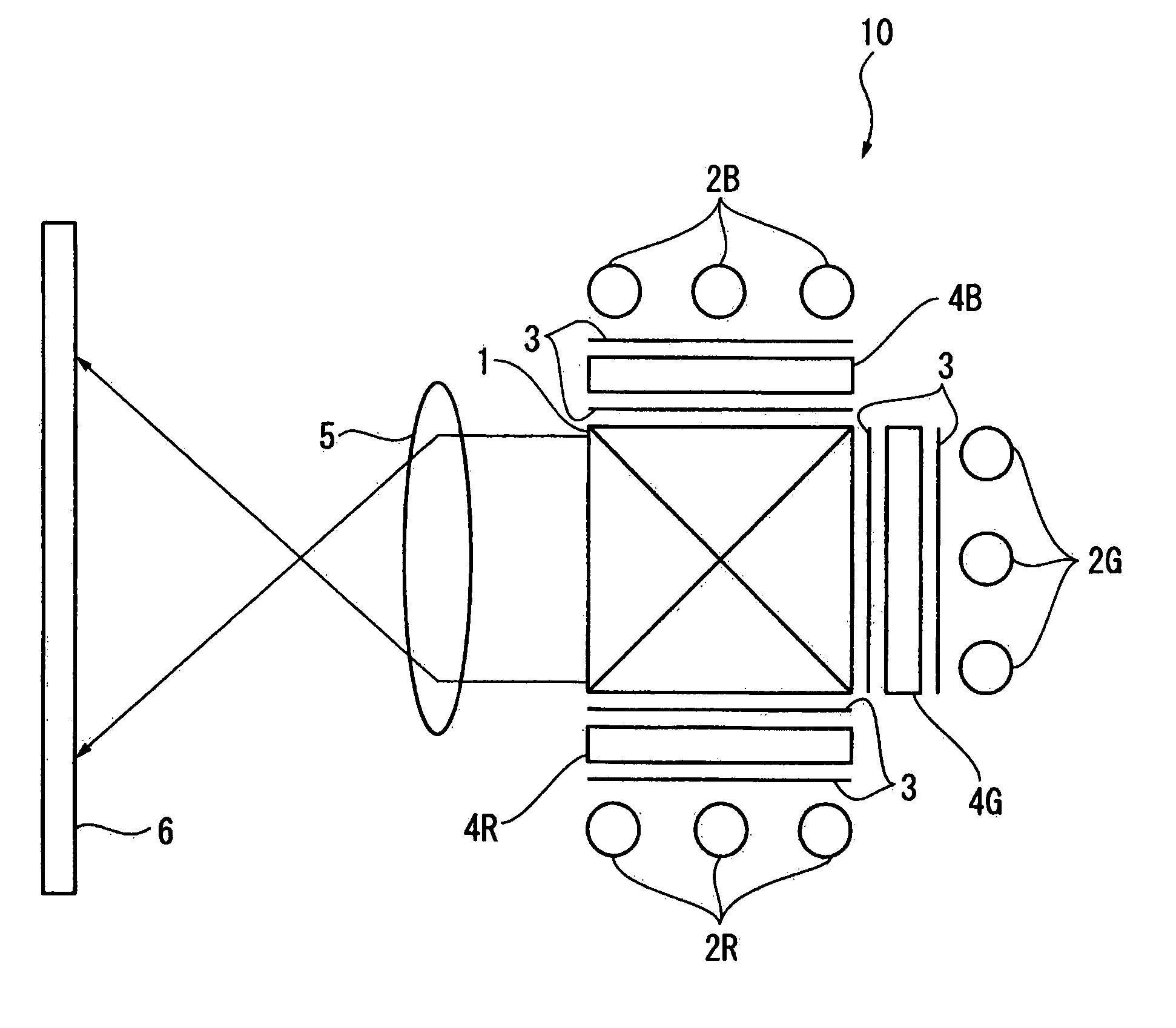
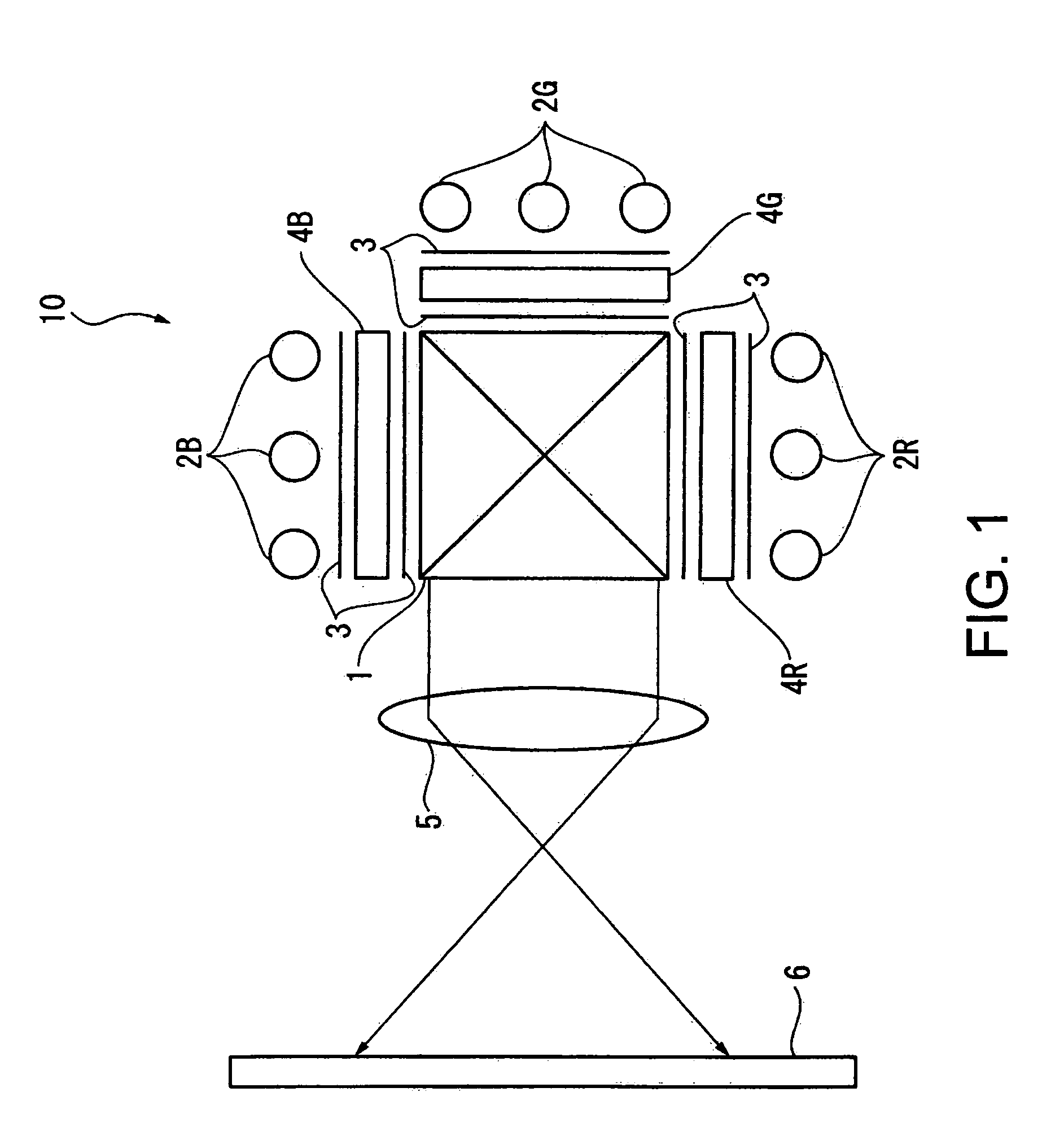
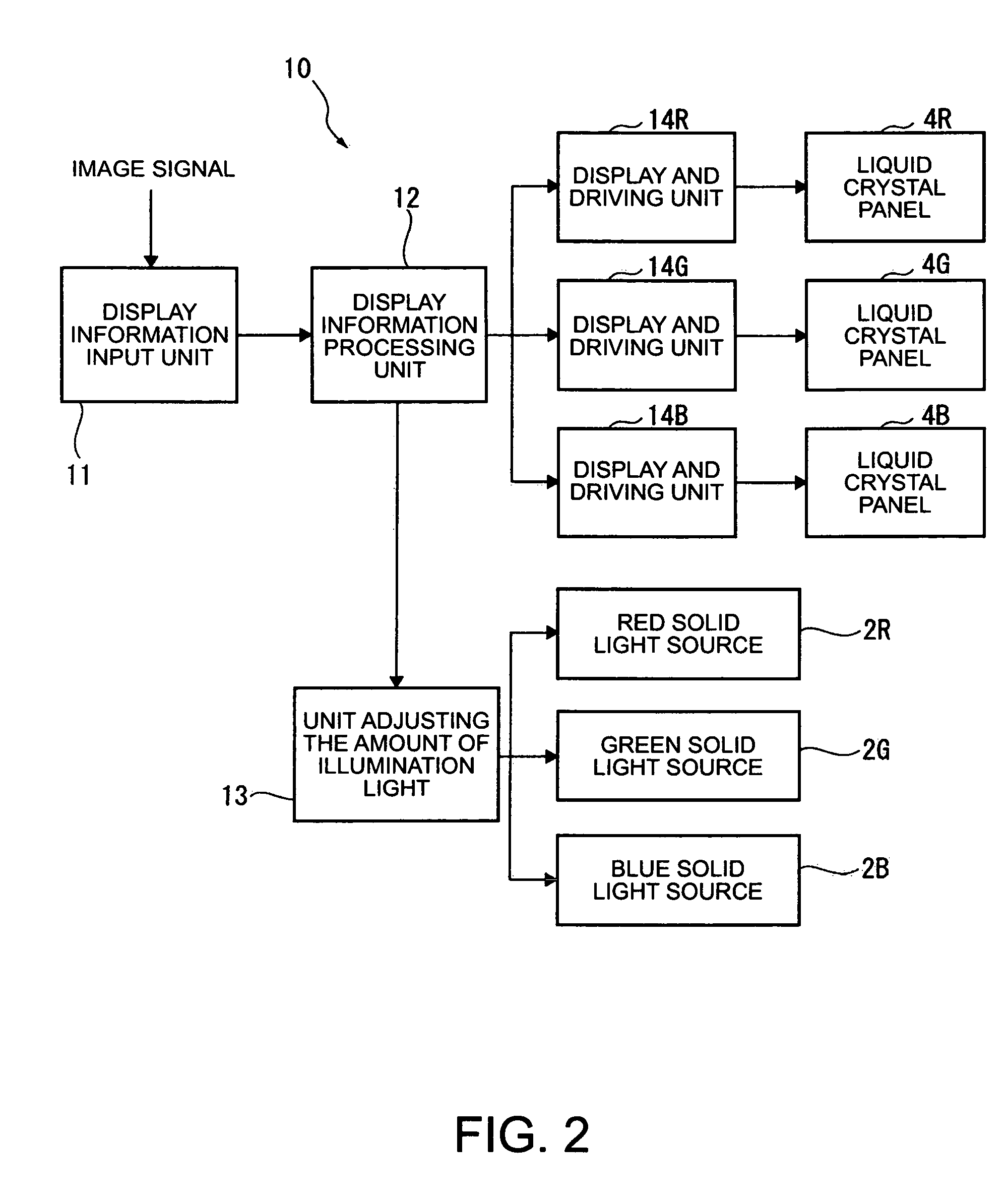
[0054]FIGS. 1 to 3 show a projection type image display device 10 according to the present embodiment. FIG. 1 is a plan view illustrating an optical system of the image display device 10 in which a liquid crystal light valve is used as an optical modulation element and a solid light source (LED (light emitting diode) light source) corresponding to each color of RGB is used to adjust the amount of illumination light with respect to the liquid crystal light valve. FIG. 2 is a block diagram illustrating the structure of the image display device 10. FIG. 3 is a block diagram illustrating the structure of a display information processing unit 12.

Configuration of Optical System of Image Display Device

[0055]As shown in FIG. 1, the optical system of the image display device 10 of the present embodiment includes a dichroic prism 1, a red solid light source 2R, a green solid li...

second embodiment

[0093]Next, a second embodiment of the invention will be described with reference to the accompanying drawings.

[0094]FIG. 9 is a block diagram illustrating the configuration of a display information processing unit 12′ in the second embodiment.

[0095]The color conversion information storage unit 123 in the first embodiment stores the plurality of 3DLUTs corresponding to the number of processes of changing the amount of illumination light determined by the brightness information. In addition, the color conversion processing unit 122 performs the color conversion process by referring to 3DLUT, which corresponds to the amount of illumination light determined by the image analysis processing unit 121, among the plurality of 3DLUTs.

[0096]On the other hand, in the second embodiment, a color conversion processing unit 122′ performs a color conversion process of calculating each RGB output value of image data by an operation using a predetermined color conversion function on the basis of eac...

third embodiment

[0111]Next, a third embodiment of the invention will be described with reference to the accompanying drawings.

[0112]FIG. 11 is a block diagram illustrating the structure of a display information processing unit 12″ in the third embodiment.

[0113]The color conversion information storage unit 123 stores the plurality of 3DLUTs corresponding to the number of processes of changing the amount of illumination light determined by the brightness information. In addition, the color conversion processing unit 122 performs the color conversion process by referring to 3DLUT, which corresponds to the amount of illumination light determined by the image analysis processing unit 121, among the plurality of 3DLUTs. In addition, the gray-scale characteristic correction of the liquid crystal light valve is performed at the same time by the color conversion process of the color conversion processing unit 122.

[0114]On the other hand, in the third embodiment, a color conversion processing unit 122″ perfo...


PUM

PropertyMeasurementUnit
brightnessaaaaaaaaaa
poweraaaaaaaaaa
opticalaaaaaaaaaa

Abstract

An image display device having an optical modulation element, which modulates light emitted from a light source according to display information, and displaying a display image based on the display information includes: a unit adjusting the amount of illumination light with respect to light emitted from the light source on the basis of brightness information on the brightness of the display image based on the display information; a color conversion processing unit that performs a color conversion process according to the brightness information with respect to the display information so that the display image can be color-reproduced within a predetermined color space; and a display and driving unit that drives the optical modulation element on the basis of the display information having been subjected to the color conversion process so as to display the display image.

Description

BACKGROUND[0001]1. Technical Field[0002]The present invention relates to an image display device, an image display method, and an image display program.[0003]2. Related Art[0004]There has been known a conventional image display device which modulates light emitted from a light source according to display information by using an optical modulation element and displays a display image based on the display information. In particular, in order to realize a liquid crystal display device of which power consumption is low and which is thin, a liquid crystal display device using a liquid crystal light valve as an optical modulation element is under development. In addition, in recent years, as one type of the liquid crystal display devices, a projection type display device (projector) or a rear surface projection type display device (projection TV), which modulates light emitted from a light source according to display information by using a liquid crystal light valve and projects the modul...

Claims


Application Information

Patent Timeline
Patent Type & Authority Patents(United States)
IPC IPC(8): G02F1/03G03B21/00
CPCH04N9/3197H04N9/3155
Inventor MIYAZAWA, YASUNAGAHASEGAWA, HIROSHIIISAKA, HIDEHITOAKAHANE, HIDEHIROTOYOOKA, TAKASHI
Owner 138 EAST LCD ADVANCEMENTS LTD
Why Eureka
Try Eureka