
Masonry wall anchoring system

a technology for anchoring systems and masonry walls, applied in the direction of fastening means, mechanical devices, building repairs, etc., can solve the problems of reducing the structural strength of the combined wall layer, exposing cement between adjacent bricks on the outer brick wall, and supporting a significant amount of the entire weight of the building structure, etc., to achieve enhanced application, reduce overall costs, and improve the performance of these auxiliary devices

Inactive Publication Date: 2008-07-29
HAYES JOHN T
View PDF36 Cites 36 Cited by
  • Summary
  • Abstract
  • Description
  • Claims
  • Application Information

AI Technical Summary

Benefits of technology

The plastic anchoring device effectively reinforces masonry walls by distributing force evenly, reducing the risk of further damage and cracking, while being cost-effective and faster to install, enhancing the structural integrity and earthquake resistance of the building.

Problems solved by technology

These walls are generally structural, and they often support a significant amount of the entire weight of the building structure.
With time, the connection between the headers and the brick wall layers crack and separate or loosen significantly reducing the structural strength of the combined wall layers.
Further, the cement between adjacent bricks on the outer brick wall exposed to the weather also cracks and separates from the surfaces of the bricks.
Eventually, these walls will deteriorate with age to the extent that the wall or portions thereof will totally fail and collapse causing major structural failure of the building.
This creates enormous shear forces throughout the height of the combined outer wall causing splitting and separation between bricks.
Further, seismic events such as earthquakes can shake apart a deteriorating wall within seconds, or even liquefy the soil supporting the footers, causing immediate catastrophic failure of the walls and potentially the entire building structure.
However, many of the mechanical anchors utilize a wedging or expanding type fastening within the hole, which can cause added damage and stresses to the combined outer wall.
When the mechanical fasteners are tightened, the expanding fastener can break or crack the surround cement and / or brick around the hole.
Additionally, these anchors are stronger than the more brittle cement and / or brick construction units and when the combination of the anchoring device and the brittle construction units are exposed to wall movement, such as would occur during an earthquake or foundation settling, this disparity in strength results in additional fracturing and / or cracking of the brittle construction units.
Further, the use of mechanical anchors is expensive and time consuming for installation purposes.

Method used


Image

  • Masonry wall anchoring system
  • Masonry wall anchoring system
  • Masonry wall anchoring system

Examples


Embodiment Construction

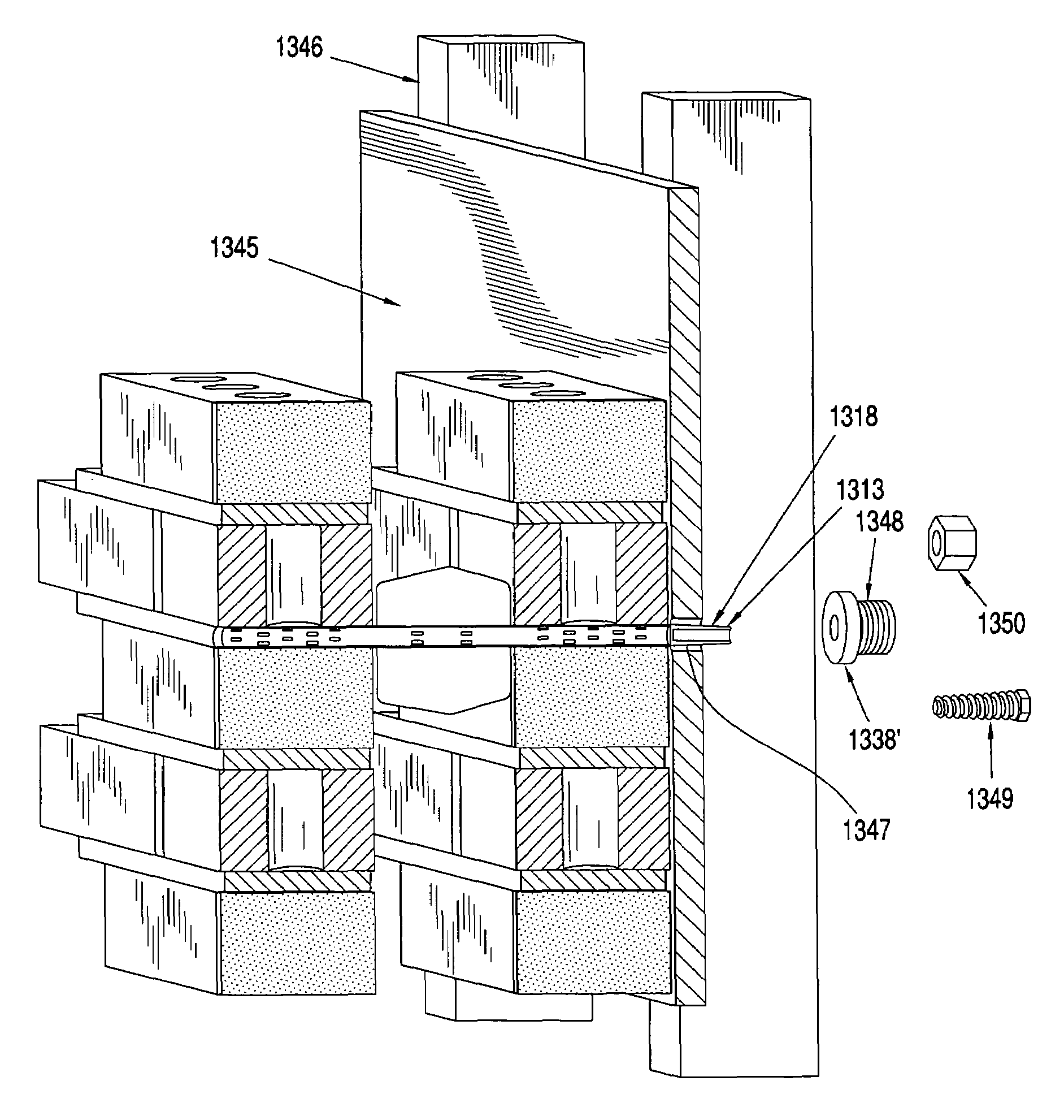
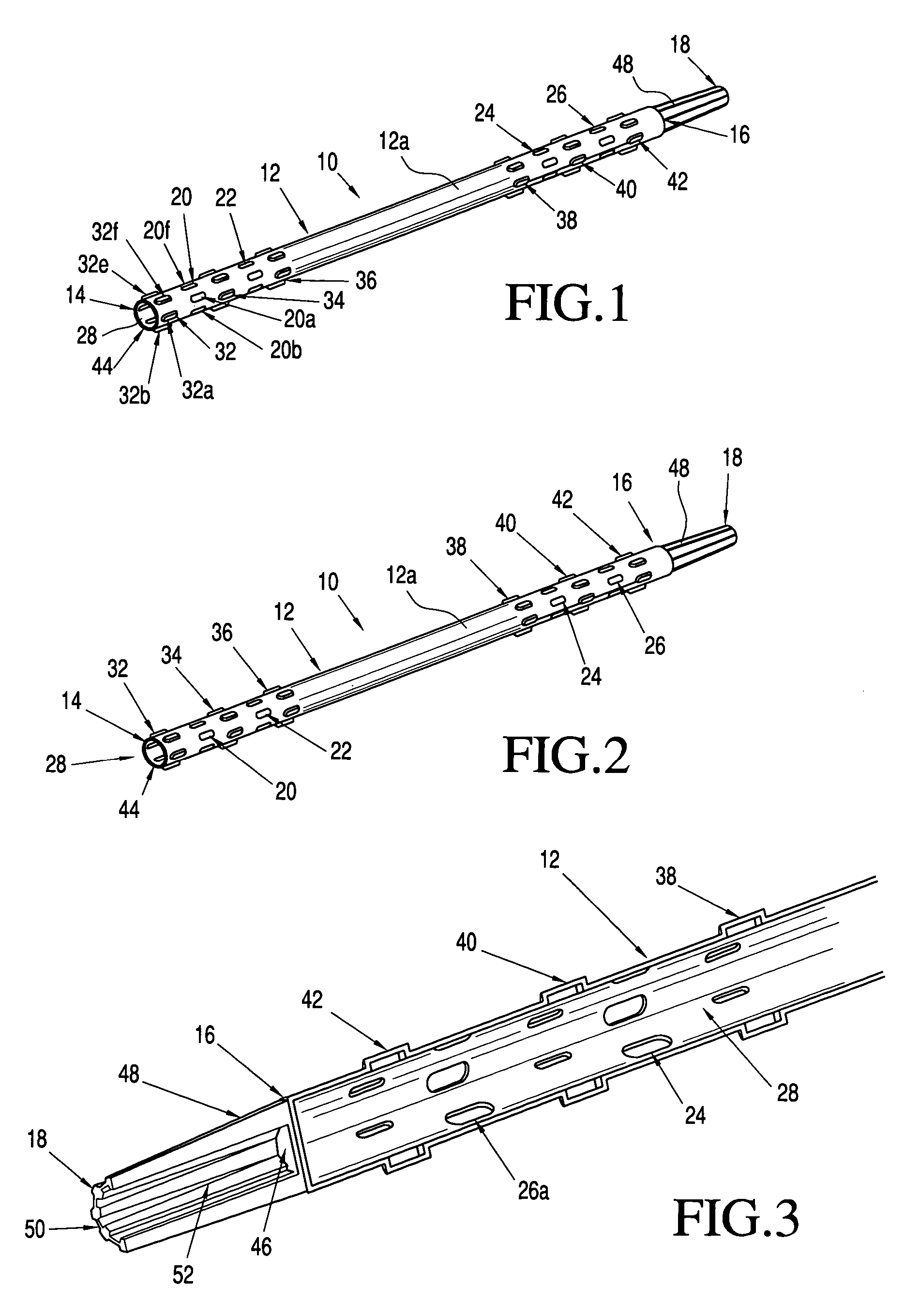
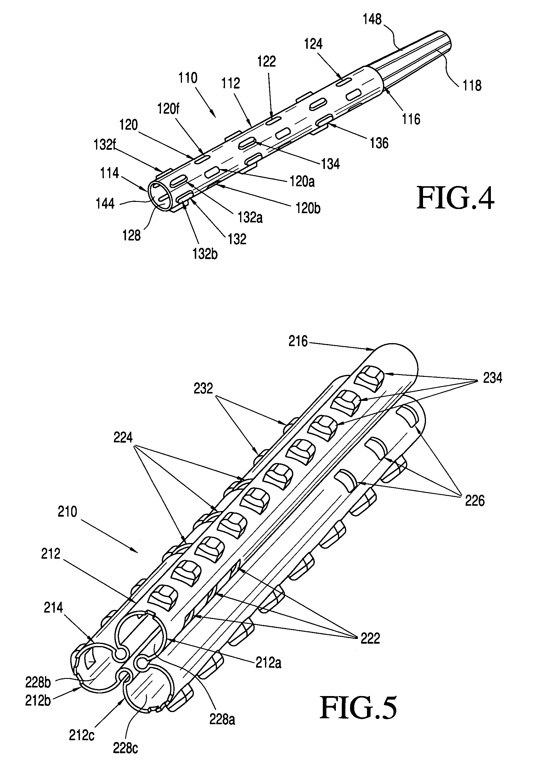
[0096]The present invention is directed to an anchoring device for strengthening, reinforcing, fixing and / or repairing masonry structures, in particular a masonry interior and exterior partition and load bearing walls. The anchoring device according to the present invention is particularly suitable for use with a single brick wall layer, or a combined brick wall structure having two (2) or more spaced apart brick wall layers. The anchoring device according to the present invention can be provided with an optional connecting end configured to connect with other structural elements or components of the building, in particular an internal or external wall structure of the building (e.g. wall sheathing, wall studs, band board, steel frame, etc.)

[0097]The anchoring device according to the present invention can be made from a wide variety of materials such as plastic, rubber, synthetic rubber, fiberglass, resin, plastic composite, metal, metal composite, ceramic, ceramic composite, phenol...


PUM


Abstract

An anchoring device configured for reinforcing and renovating an existing masonry wall. The anchoring device is preferable a plastic anchoring device configured to be inserted in a hole in the existing masonry wall, and then preferable expanded to securely anchor same.

Description

FIELD OF THE INVENTION[0001]The present invention is directed to a device, system and method for anchoring a masonry wall, in particular for reinforcing an existing masonry wall.BACKGROUND OF THE INVENTION[0002]Typically older brick buildings built during the past two-hundred and fifty (250) years have traditionally combined outer brick walls made of two (2) or more spaced apart brick wall layers. These wall layers are typically connected by cross-turned joining members called “headers”. The spacing between the layers is typically left unfilled or filled with construction rubble or cement. The headers connect the outer brick wall layer to the inner brick wall layer(s). These walls are generally structural, and they often support a significant amount of the entire weight of the building structure. With time, the connection between the headers and the brick wall layers crack and separate or loosen significantly reducing the structural strength of the combined wall layers. Further, the...

Claims


Application Information

Patent Timeline
Patent Type & Authority Patents(United States)
IPC IPC(8): E04B1/38E04B1/41E04C5/07E04G23/02F16B13/14
CPCE04B1/4185F16B13/141E04G23/0222E04C5/07
Inventor HAYES, JOHN T.
Owner HAYES JOHN T
Learn More