
Frame grabber

a frame data and frame technology, applied in the field of frame data grabbers, can solve the problems of insufficient conditions, difficult to transfer the complete frame data to the main image processor, and insufficient conditions of conventional frame data grabber technology and products, etc., and achieve the effect of high system performance and simple image-based operation

Active Publication Date: 2008-07-29
HONDA MOTOR CO LTD
View PDF7 Cites 2 Cited by
  • Summary
  • Abstract
  • Description
  • Claims
  • Application Information

AI Technical Summary

Benefits of technology

This solution enables parallel operation with the master controller, reduces processing time, ensures reliable image data transfer, and optimizes image acquisition, enhancing complex image-based operations and system performance.

Problems solved by technology

However, the conventional frame grabber has the following technical problems for each feature as described above.
For (3), when the main image processor cannot obtain the frame data due to a trouble of DMA transferring, a part of frame data is not acquired and missing some of the sequential frame data so that a complete set of the frame data is difficult to be transferred to the main image processor for post processing.
For (4), the on-off control of the light or illumination to the objective cannot provide sufficient conditions to take the image of the objects in terms of contrast and the extraction of the reflection from the objects for the purpose of post process of the images.
All these problems are substantially caused from the fundamental design concept of frame grabbers, that is, real-time capability to fully support the high priority of image acquisition, slave operation for the master controller and asynchronous operation to support the real-time operation and independent operation for image acquisition.
This design concept allows the versatile usage or application of the frame grabbers, but is not sufficient for specific application such as; parallel synchronization to the frame grabber necessary for additional processing to the master controller, wide processing window time but small acquired image frames required, more reliable image data transferring required than toggle buffer memories used for the DMA and simultaneous acquisition of multi-conditional images required.
The conventional frame grabber technology and products have not satisfied these requirements which are necessary for complex image-based operation and high system performances.

Method used


Image

  • Frame grabber
  • Frame grabber
  • Frame grabber

Examples


Embodiment Construction

[0029]The embodiments of the present invention are explained by using the figures.

(Construction of Frame Grabber System)

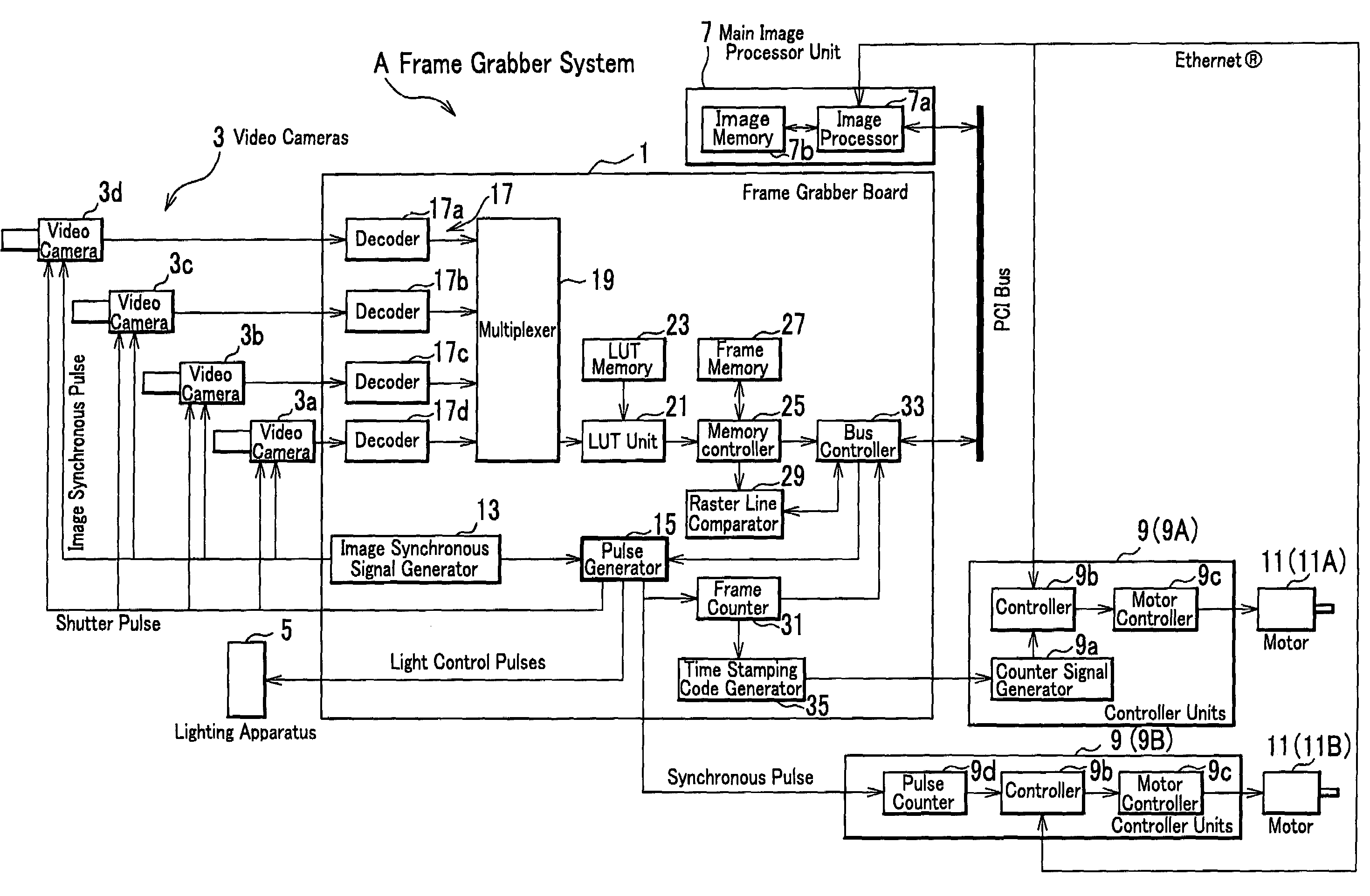
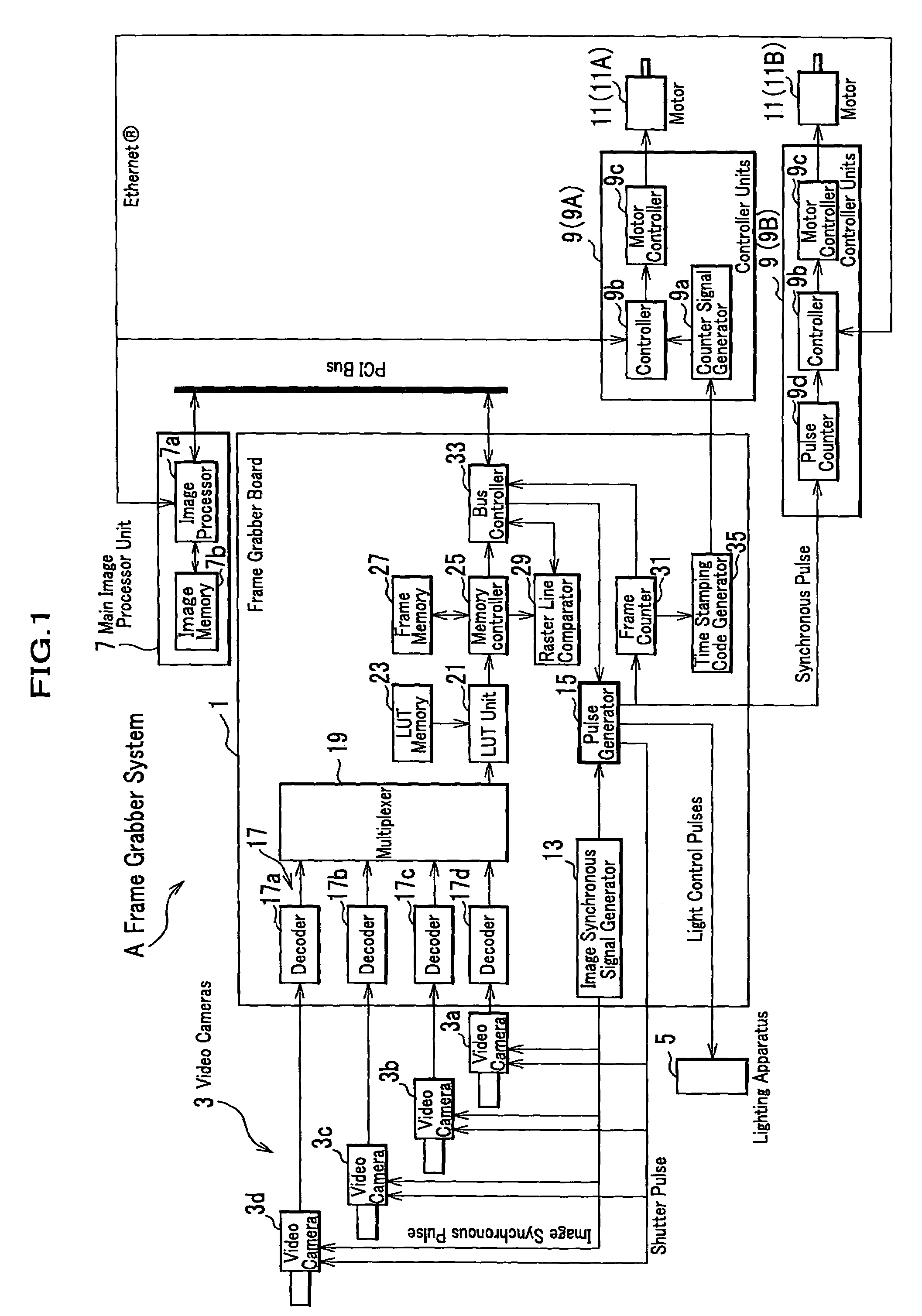
[0030]The FIG. 1 shows the block diagram of the frame grabber system including a frame grabber board, a main image processor and controllers used for a walking robot. Specifically, the frame grabber system A comprises the frame grabber board 1, video cameras 3, a lighting apparatus 5, a main image processor unit 7 and controller units 9 (9A and 9B).

[0031]This frame grabber system A is installed in, for example, a walking robot (not shown in details). The lighting apparatus 5 can be adjustable in the intensity of the shining light. The walking robot takes raw images of the objects (for example, obstacles) which are in the fore position of his advancing direction by means of cameras 3. The frame grabber board 1 converts the raw images into digital images in a manner of frames which are transferred to the main image processor unit and outputs a series of synchronous s...


PUM


Abstract

A frame grabber comprising image signal decoders to convert the analog image signal to digital image data, a multiplexer to select the image data stream sent from the image signal decoders, frame memories and a memory controller to control the digital image data in a unit of frame data to be transferred to an external main image processor unit further has a pulse generator, a pulse counter, a bus controller for transferring the frame data and a time stamping code generator to consolidate the same time base between the in-frame image data and other data used for robot controlling.

Description

FIELD OF THE INVENTION[0001]The present invention relates to a frame grabber that takes substantially time-varying images taken by video cameras and converts them into signals that image data processors can handle.DESCRIPTION OF THE RELATED ART[0002]An image processing technology called a frame grabber, that is to convert the analog or digital image taken by plural video cameras into digital image data and output them to digital image processors, is well know.[0003]The conventional frame grabber technologies have the following features as (1) to (4) regarding synchronous operation and asynchronous operation;[0004](1) a frame grabber can take an image in a frame in synchronous to external signals which are generated by a processor other than a main image processor that receives such framed image from the frame grabber wherein the synchronization is carried out in accordance with the bus clock signal,[0005](2) a frame grabber has a capability to react to the interruption raised by an ...

Claims


Application Information

Patent Timeline
Patent Type & Authority Patents(United States)
IPC IPC(8): H04N5/235H04N5/04H04N5/222H04N5/225H04N5/232
CPCH04N5/2256H04N5/2354H04N5/232H04N23/56H04N23/60H04N23/74H04N5/04
Inventor AOYAMA, CHIAKI
Owner HONDA MOTOR CO LTD
Learn More