
Method and apparatus for air treatment

Inactive Publication Date: 2008-08-05
THE JOHN HOPKINS UNIV SCHOOL OF MEDICINE
View PDF22 Cites 47 Cited by
  • Summary
  • Abstract
  • Description
  • Claims
  • Application Information

AI Technical Summary

Benefits of technology

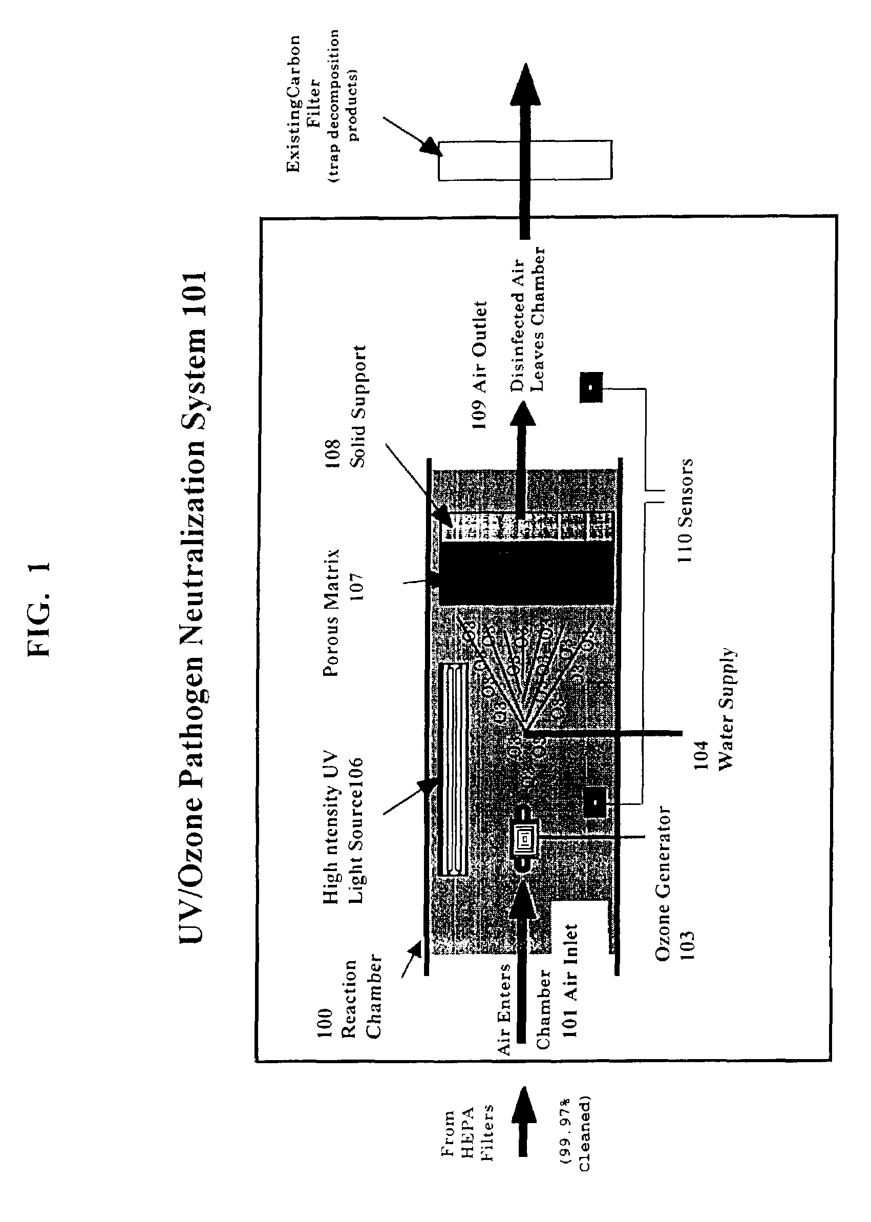
[0013]The present inventions provide an apparatus and methods for neutralizing airborne pathogens in large volumes of ventilated air in real time, which is effective against airborne pathogenic bacteria, spores and viruses. The technology is based on the formation of highly reactive ozone intermediates that form when ozone reacts with water vapor in the presence of ultraviolet light inside a flow-through reaction chamber into which contaminated room air is introduced. The highly active free radical ozone intermediates react with the pathogens in the air to neutralize them, thereby disinfecting the air. The pathogen neutralization system of the present invention can be easily installed in commercial and residential HVAC air handling systems and it uses commercially available components.

Problems solved by technology

The risk to patients of becoming infected with Staphylococcus, one of the most common and deadly infections associated with prolonged hospital stay, is significant.
The neutralization system of airborne biological pathogens is a very difficult problem to solve because many of the agents are highly resistant to traditional neutralization methods that have thus far been primarily useful to disinfect surfaces.
Ozone is a highly effective disinfectant in water and on surfaces, but the use of ozone as a disinfectant to neutralize pathogens in air has not been demonstrated before.
However, to date, no commercial HVAC system have been developed that uses ozone to disinfect airborne pathogens.
Instead, the UV radiation damages the DNA in the pathogen so that it cannot reproduce.
However, all of these systems depend on dissolving ozone in water to destroy the pathogens.
So far there is no effective way to disinfect or neutralize airborne pathogens in large volumes of contaminated air in real time to protect citizens against a terrorist attack using biological weapons, or to disinfect air in hospitals.

Method used


Image

  • Method and apparatus for air treatment
  • Method and apparatus for air treatment
  • Method and apparatus for air treatment

Examples


example 1

A. The Neutralization System

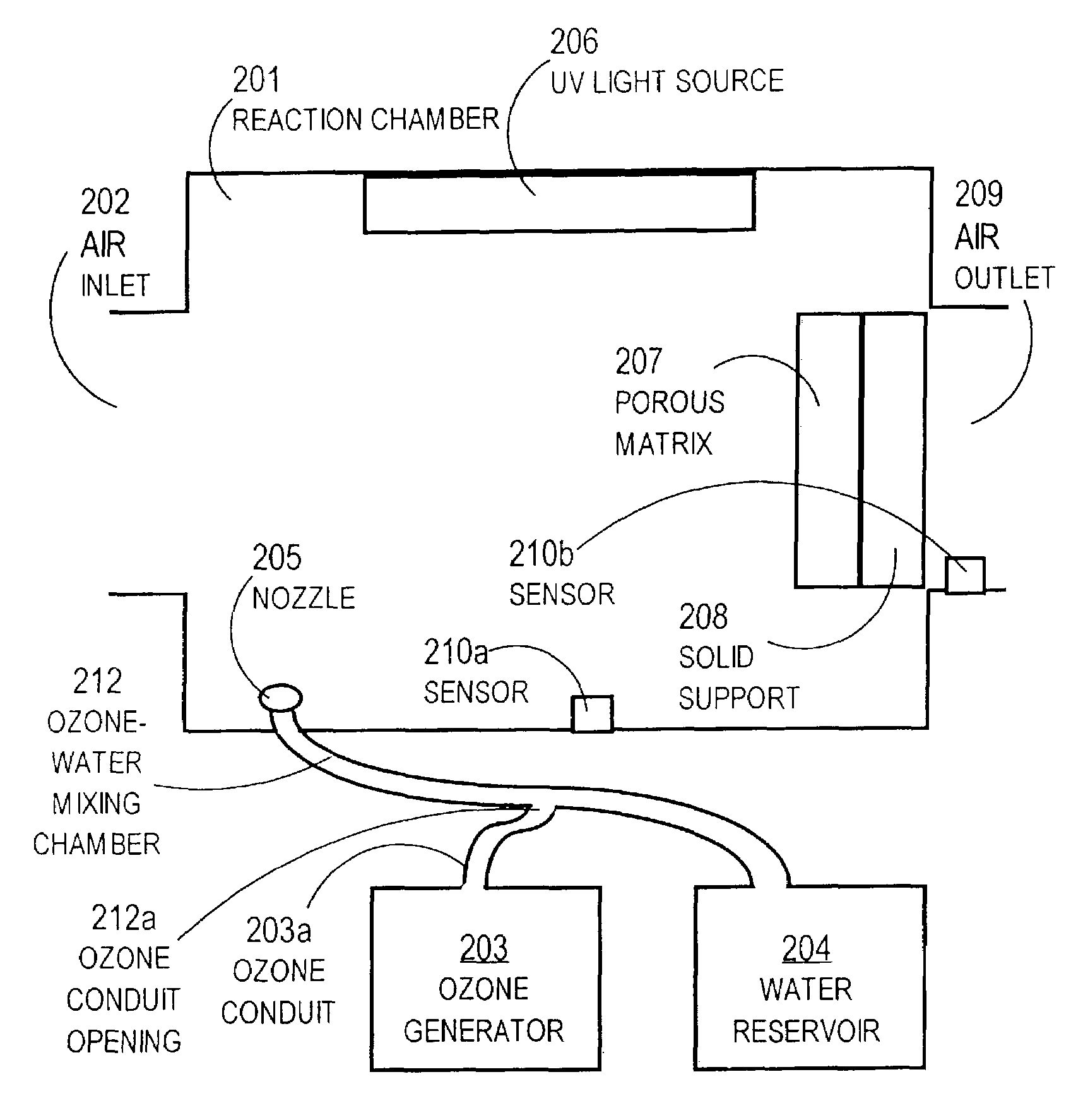
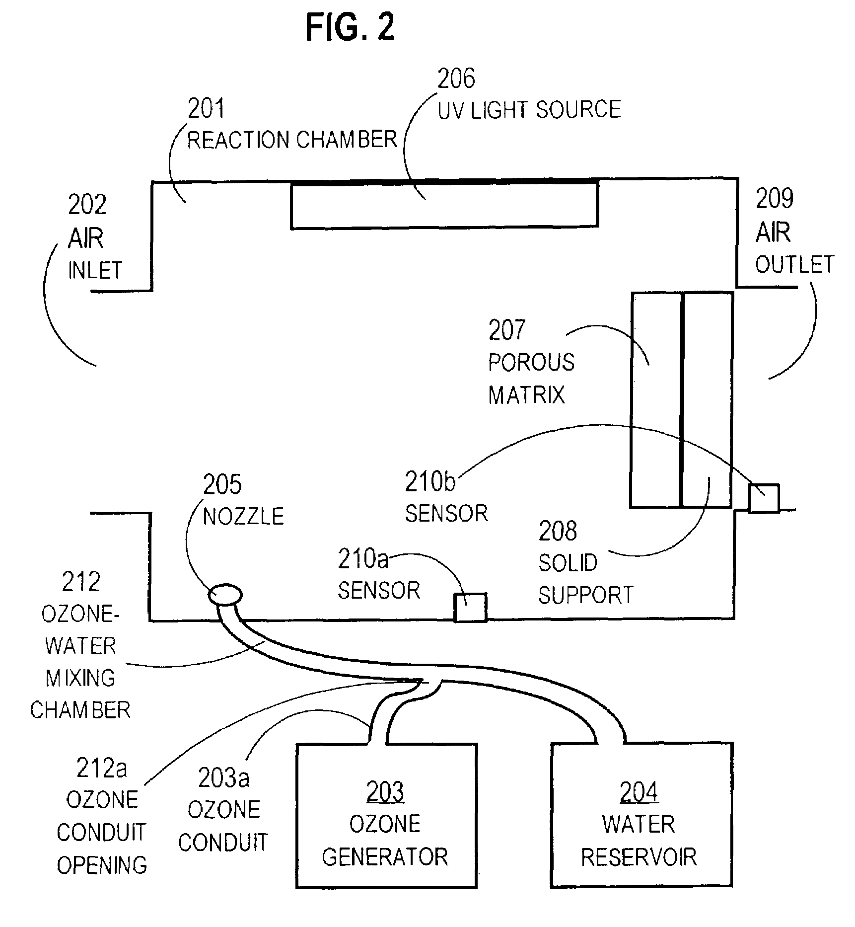
[0089]The neutralization system used in this experiment is shown in FIG. 2, with the exception that the solid support 208 with ozone removal catalysts was not included, and the system also included a fan to help pull air through the system. The fan was turned on in all experiments. A CD-5 GENESIS™ corona discharge ozone generator made by Del Industries, Inc. with maximum output of 5 g / hr was disposed outside the reaction chamber as shown in FIG. 2. Downstream from the ozone generator 203 and ozone conduit 203a, is a water reservoir 204 that releases a stream of water into the water / ozone conduit 212. As the water stream flows through the water / ozone conduit, it creates a vacuum that helps to pull the ozone gas exiting the ozone generator 203 through ozone conduit 203a into the water / ozone conduit 212 at conduit opening 212a. The UV light source (206 consisted of two BioAire —UV Lights Model BUV 24DE Double Ended Fixtures. The brand of light is not critica...

example 2

The UV / Ozone Pathogen Neutralization System Completely Eliminated Large Amounts of Airborne Vegetative Cells of Erwinia

[0095]The neutralization system was set up as described in Example 1. Various experiments were designed to assess the ability of the system to neutralize airborne Erwinia herbicola bacteria. In all experiments, air was passed through the system for thirty minutes while the system fan was continuously on. In certain of these experiments, large amounts of airborne vegetative cells of Erwinia herbicola bacteria (about 5.3×10⁹ CFU / ml) were introduced into the air entering the reaction chamber through the air inlet as is described in Example 1B using a MICRO MIST™ nebulizer. Incoming air (with or without Erwinia herbicola) was sampled continuously just before entering the neutralization system via the air inlet, and outgoing air was sampled just as it leaves the system, as described in Example 1.

[0096]In FIGS. 5A-H, System inlet and System outlet plates (dishes) were con...

example 3

[0101]Large amounts of airborne vegetative cells of Bacillus globigii (13G) spores (a simulant for the anthrax spores), were introduced into the chamber air inlet of a neutralization system as described in Example 1 using a MICRO MIST™ nebulizer under several different sets of conditions. Bacillus globigii spores are known to be particularly difficult to neutralize. In all experiments, air was passed through the system for thirty minutes while the system fan was continuously on.

Control-No Spores, All Systems Off-Fan Only

[0102]As a control, room air was drawn through an inactive neutralization system before any spores were intentionally introduced. The water was off, the ozone generator was off, and the UV light was off. Both the System inlet plates exposed to incoming air and System outlet plates exposed to outgoing air that had passed through the inactivated neutralization system, showed no growth of bacteria after the thirty minutes that air was passed through the reaction chamber...


PUM


Abstract

A method and apparatus is described for neutralizing airborne pathogens in ventilated air, and in heating or air conditioning systems. The pathogen neutralization system is effective against a wide spectrum of pathogens, it incorporates commercially available components, and it can be readily integrated into commercial HVAC systems where it neutralizes airborne pathogens in large volumes of ventilated air in real time without any chemical reagents. Typically, the system has a flow-through reaction chamber that contains a UV light source that emits short intense flashes of broad-spectrum UV light, a source of water vapor or spray, and an ozone generator. The system generates highly reactive ozone intermediates by irradiating ozone gas with UV light in the presence of water droplets or water vapor. The pathogens that can be neutralized by this system include bacteria, viruses, spores, fungi and parasites.

Description

CROSS-REFERENCE TO RELATED APPLICATION[0001]This application claims the benefit of prior filed co-pending U.S. Provisional Application Ser. No. 60 / 327,192, filed Oct. 4, 2001, which is incorporated herein by reference.BACKGROUND OF THE INVENTION[0002]1. Field of the Invention[0003]The present invention relates to a new, safe, effective method to neutralize or destroy a wide range of airborne pathogens (spores, bacteria and viruses) in commercial HVAC air handling systems.[0004]2. Description of the Related Art[0005]It is critical to develop rapid, effective, and safe (nontoxic and noncorrosive) pathogen neutralization technologies to protect civilian and military facilities from a chemical or biological attack. Within this area, emphasis is on the pathogen neutralization of domed stadiums, subways, and enclosed facilities (buildings and command centers that may contain extremely sensitive equipment. This effort is a key to eliminate the threat of biological weapons in the planning a...

Claims


Application Information

Patent Timeline
IPC IPC(8): A61L9/00A61L9/015A61L9/14A61L9/20B01J19/12B64D13/00F24F8/22F24F8/26
CPCA61L9/015A61L9/145A61L9/20B01J19/123F24F3/16B64D13/00A61L2209/212F24F2221/44F24F2003/1667F24F2003/1671F24F2003/1685F24F8/26F24F8/40F24F8/22
Inventor POTEMBER, RICHARD S.BRYDEN, WAYNE A.
Owner THE JOHN HOPKINS UNIV SCHOOL OF MEDICINE
Learn More