Method and apparatus to control radiation tube focal spot size

a technology of xray tube and focal spot, which is applied in the field of radiographic equipment, can solve the problems of no control of the variation of the focal spot size, image quality, and artifacts in images produced by ct imaging systems utilizing such tubes

Active Publication Date: 2008-08-05
GENERAL ELECTRIC CO
View PDF22 Cites 16 Cited by
  • Summary
  • Abstract
  • Description
  • Claims
  • Application Information

AI Technical Summary

Benefits of technology

[0012]It will be observed that some configurations of the present invention allow a focal spot to be maintained at a given size over a wide range of mA and kV values. Also, some configurations permit the size and shape to be optimized to allow the x-ray tube to operate at the highest peak power possible, without having to limit the power to account for variations in the spot size.

Problems solved by technology

As a result, artifacts can occur in images produced by a CT imaging system utilizing such tubes.
For known prior art CT imaging systems, there is no way to control this variation other than use an an x-ray tube designed to keep the focal spot size within a given range.
If the designed range is too wide, image quality, tube performance, or both may be degraded.
In particular, as CT imaging systems are being built with increasingly wide detectors and thin slices, variations in spot size with mA is causing increasingly noticeable artifacts in outer rows of volume computed tomographic (VCT) images.

Method used


Image

  • Method and apparatus to control radiation tube focal spot size
  • Method and apparatus to control radiation tube focal spot size
  • Method and apparatus to control radiation tube focal spot size

Examples


Embodiment Construction

[0020]As used herein, an element or step recited in the singular and proceeded with the word “a” or “an” should be understood as not excluding plural said elements or steps, unless such exclusion is explicitly recited. Furthermore, references to “one embodiment” of the present invention are not intended to be interpreted as excluding the existence of additional embodiments that also incorporate the recited features.

[0021]Also as used herein, the phrase “reconstructing an image” is not intended to exclude embodiments of the present invention in which data representing an image is generated but a viewable image is not. However, many embodiments generate (or are configured to generate) at least one viewable image.

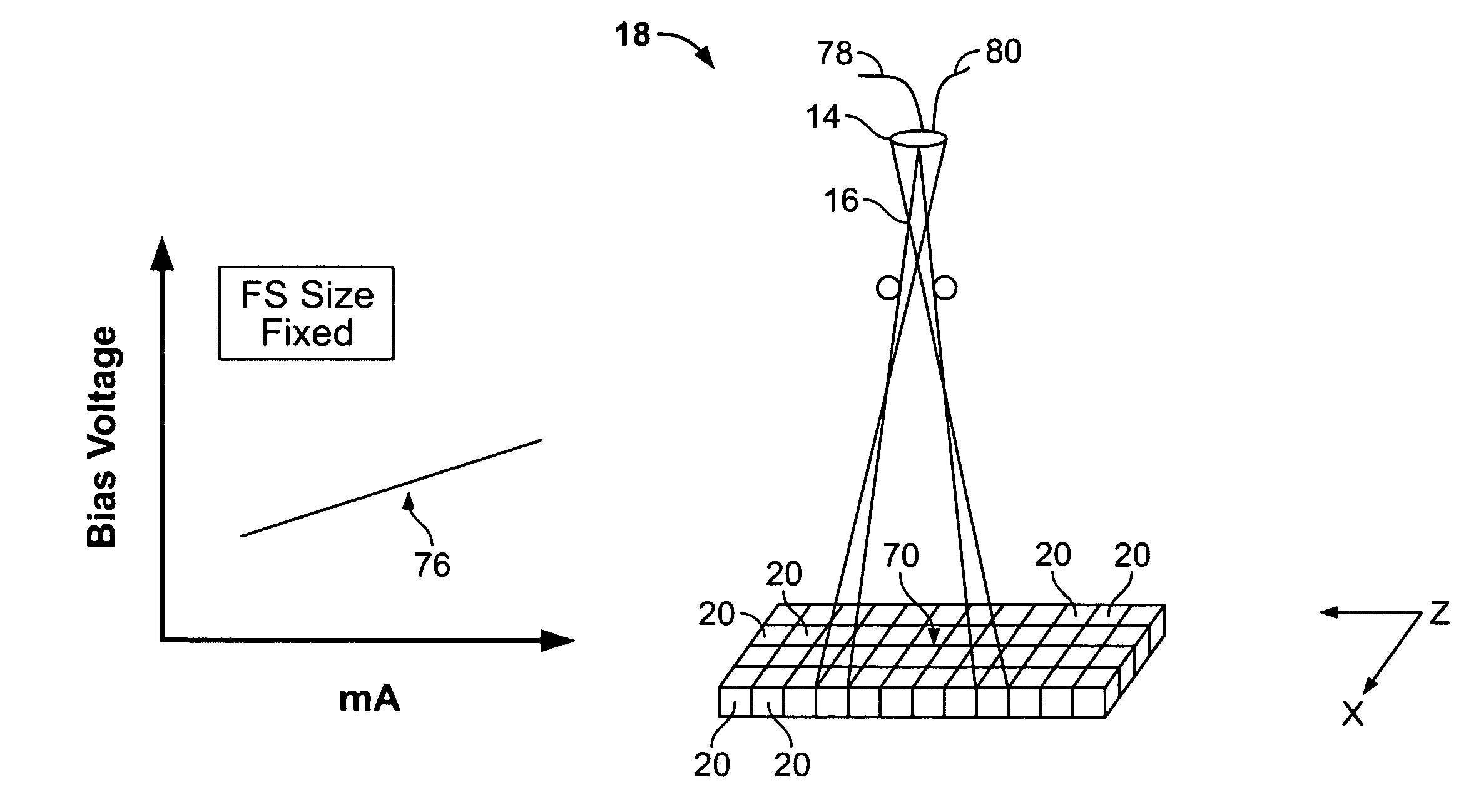
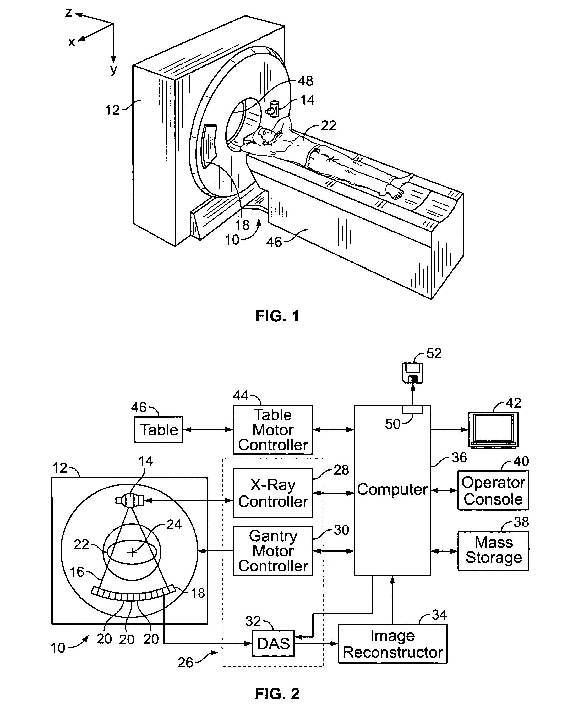
[0022]Referring to FIGS. 1 and 2, a multi-slice scanning imaging system, for example, a Computed Tomography (CT) imaging system 10, is shown as including a gantry 12 representative of a “third generation” CT imaging system. Gantry 12 has an x-ray tube 14 (also called x-ray sou...


PUM


Abstract

A method for controlling focal spot size changes of an x-ray source in an imaging system includes measuring focal spot sizes as a function of a plurality of x-ray source operating parameters, determining a calibration table or transfer function utilizing the measured focal spot sizes as a function of the plurality of x-ray tube operating parameters, and utilizing the calibration table or transfer function to control focal spot size variations during operation of the imaging system.

Description

BACKGROUND OF THE INVENTION[0001]This invention relates generally to radiation imaging devices, and more particularly to methods and apparatus for controlling a focal spot of an x-ray tube of an imaging apparatus.[0002]In some known CT imaging system configurations, an x-ray source, such as an x-ray tube, projects a fan-shaped beam which is collimated to lie within an X-Y plane of a Cartesian coordinate system and generally referred to as an “imaging plane”. The x-ray beam passes through an object being imaged, such as a patient. The beam, after being attenuated by the object, impinges upon an array of radiation detectors. The intensity of the attenuated radiation beam received at the detector array is dependent upon the attenuation of an x-ray beam by the object. Each detector element of the array produces a separate electrical signal that is a measurement of the beam intensity at the detector location. The intensity measurements from all the detectors are acquired separately to pr...

Claims


Application Information

Patent Timeline
Patent Type & Authority Patents(United States)
IPC IPC(8): H05G1/32H05G1/34H05G1/46
CPCA61B6/032H05G1/26H01J35/14A61B6/027H01J35/147
Inventor DUNHAM, BRUCE MATTHEWSCHMIDT, JONATHAN RICHARDLEMAITRE, SERGIO
Owner GENERAL ELECTRIC CO
Why Eureka
Try Eureka