
Flashlight with automatic light intensity adjustment means

a technology of automatic adjustment and flashlight, which is applied in the direction of electric lighting with batteries, semiconductor devices for light sources, lighting and heating apparatus, etc., can solve the problem of saving users the trouble of manually adjusting the light intensity, and achieve the effect of low manufacturing cost and simple structur

Active Publication Date: 2008-08-12
KAPER INDAL
View PDF8 Cites 50 Cited by
  • Summary
  • Abstract
  • Description
  • Claims
  • Application Information

AI Technical Summary

Benefits of technology

[0004]In view of the aforesaid disadvantages now present in the prior art, the present invention provides a flashlight capable of detecting the intensity of light as reflected by the nearest object facing the light source of the flashlight and automatically adjusting the light intensity according to the light intensity of light as detected by the flashlight. In principle, the farther away an object is located from the light source of the flashlight, the less intense is the light reflected by the object, and the flashlight is automatically adjusted to provide stronger light. Furthermore, the lower the reflectivity of the surface of the object, the less intense is the light reflected by the object and the flashlight is automatically adjusted to provide stronger light. The present invention therefore provides users with optimal level of lighting in the dark without blinding users with bright light. The automatic adjustment means also saves users the trouble of manually adjusting the light intensity.

Problems solved by technology

The automatic adjustment means also saves users the trouble of manually adjusting the light intensity.

Method used


Image

  • Flashlight with automatic light intensity adjustment means
  • Flashlight with automatic light intensity adjustment means
  • Flashlight with automatic light intensity adjustment means

Examples


first embodiment

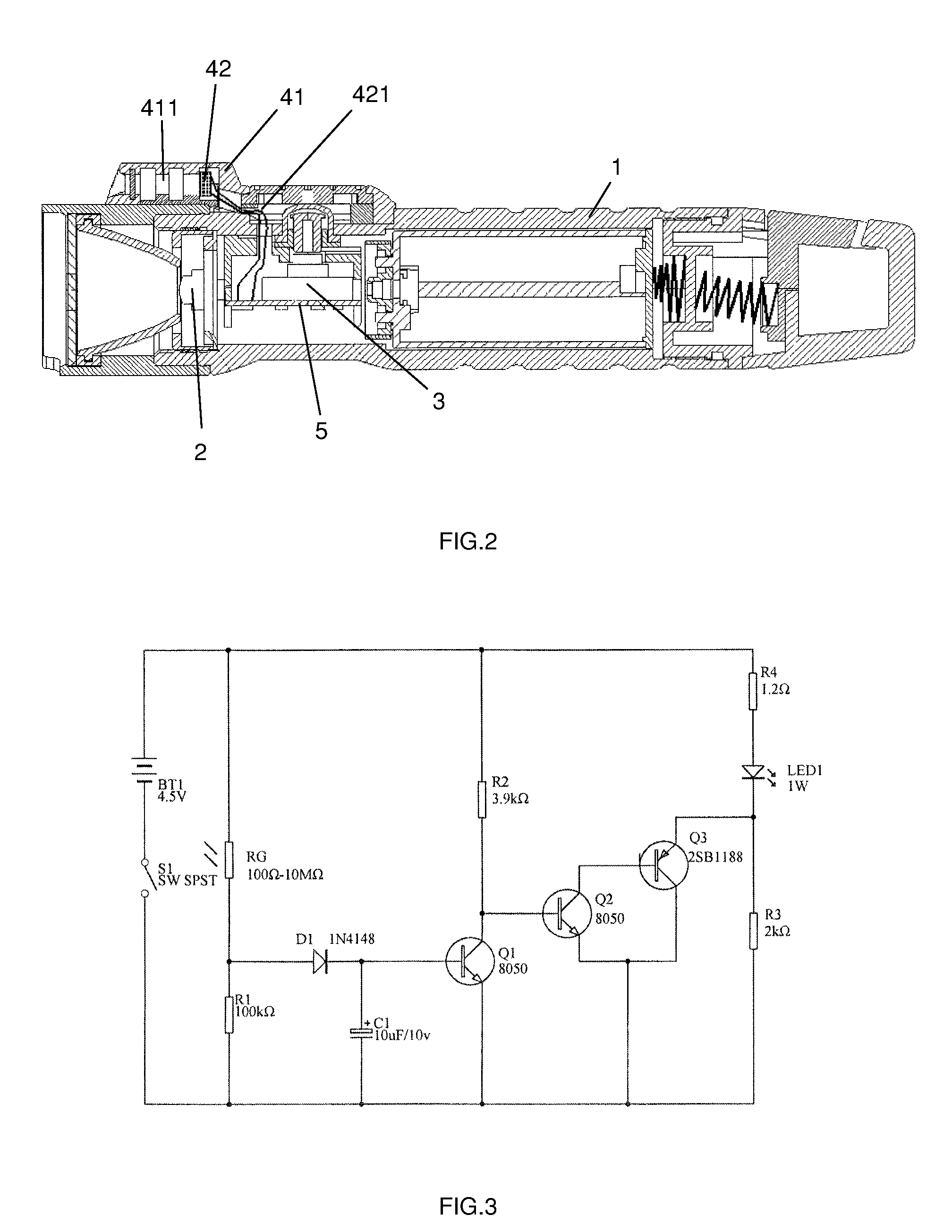
[0029]FIG. 3 further illustrates the circuit diagram of the light controlling circuit of the As illustrated in FIG. 3, the light controlling circuit comprises batteries BT1, switch S1, photoresistor RG, light emitting diode LED1, resistors R1, R2, R3 and R4, a diode D1, a capacitor C1, a PNP transistor Q3, and two NPN transistors Q1 and Q2. The batteries BT1 (which constitute the power source) is connected to the light emitting diode LED1 (which constitutes the light source 2) through the switch S1 (which constitutes the switch 3). The photoresistor RG and the resistor R1 function as a voltage divider to control the voltage of the positive pole of the diode D1. The diode D1, the capacitor C1 and the NPN transistor Q1 and the resistor R2 function as a time delay circuit. The NPN transistor Q2 and the PNP transistor Q3 function as a current amplifying circuit. The resistors R4 and R3 form a current limiting circuit. When the incident light intensity detected by the photoresistor RG i...

fourth embodiment

[0033]FIG. 6 shows a block diagram of the present invention. In this embodiment, the light controlling circuit takes the form of an integrated circuit which is preset with one or more incident light intensity threshold levels, each of which corresponds to a preset level of electrical current to be controlled by the integrated circuit to pass through the light source. In this embodiment, two incident light intensity threshold levels are preset in the integrated circuit. When the incident light intensity detected is below the lower threshold level, the integrated circuit controls the electrical current passing through the light source to be at the highest level. When the incident light intensity level detected is between the lower threshold level and the higher threshold level, the integrated circuit controls the electrical current passing through the light source to be at the middle level. When the incident light intensity level detected exceeds the higher threshold level, the integr...


PUM


Abstract

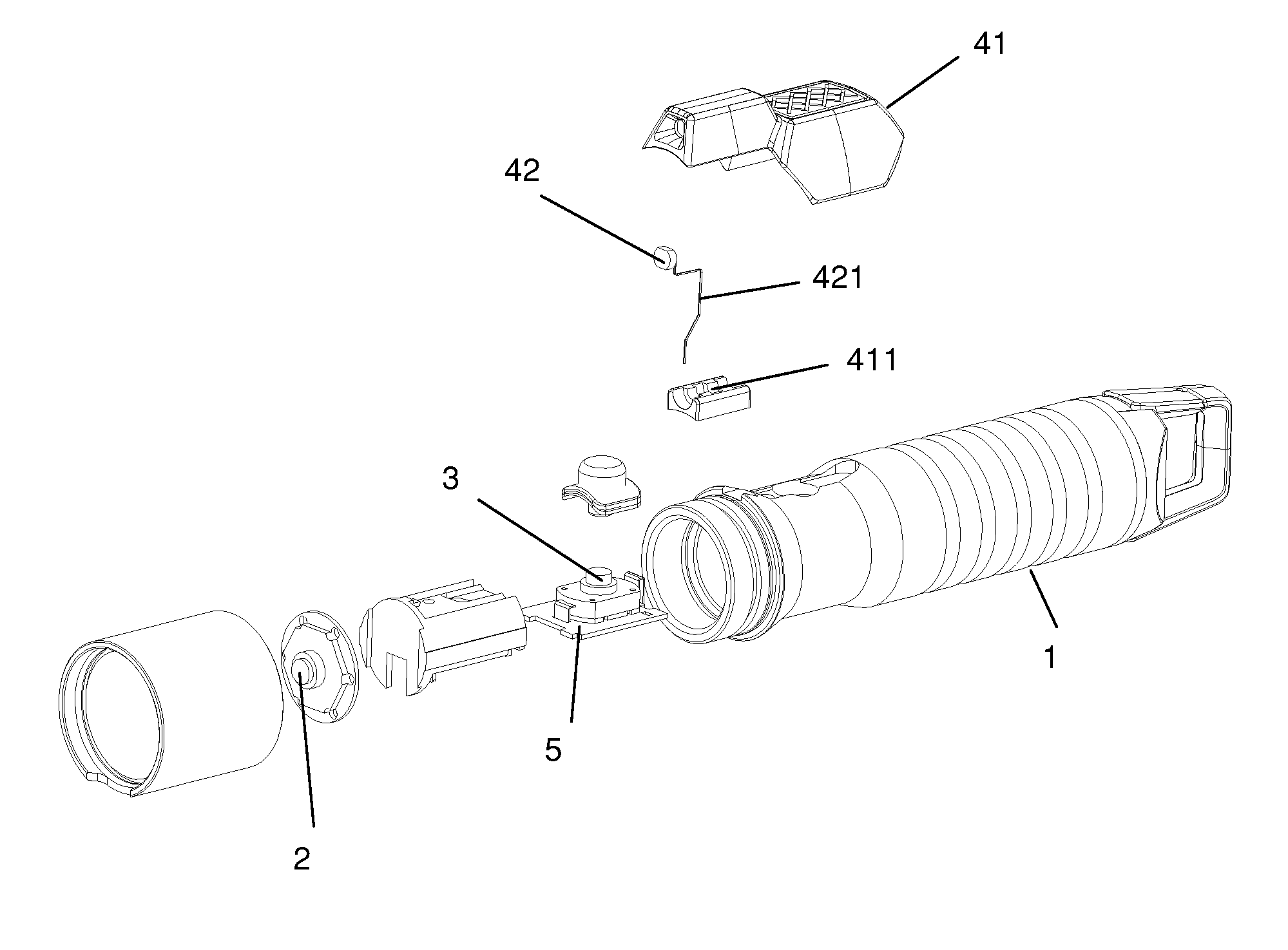
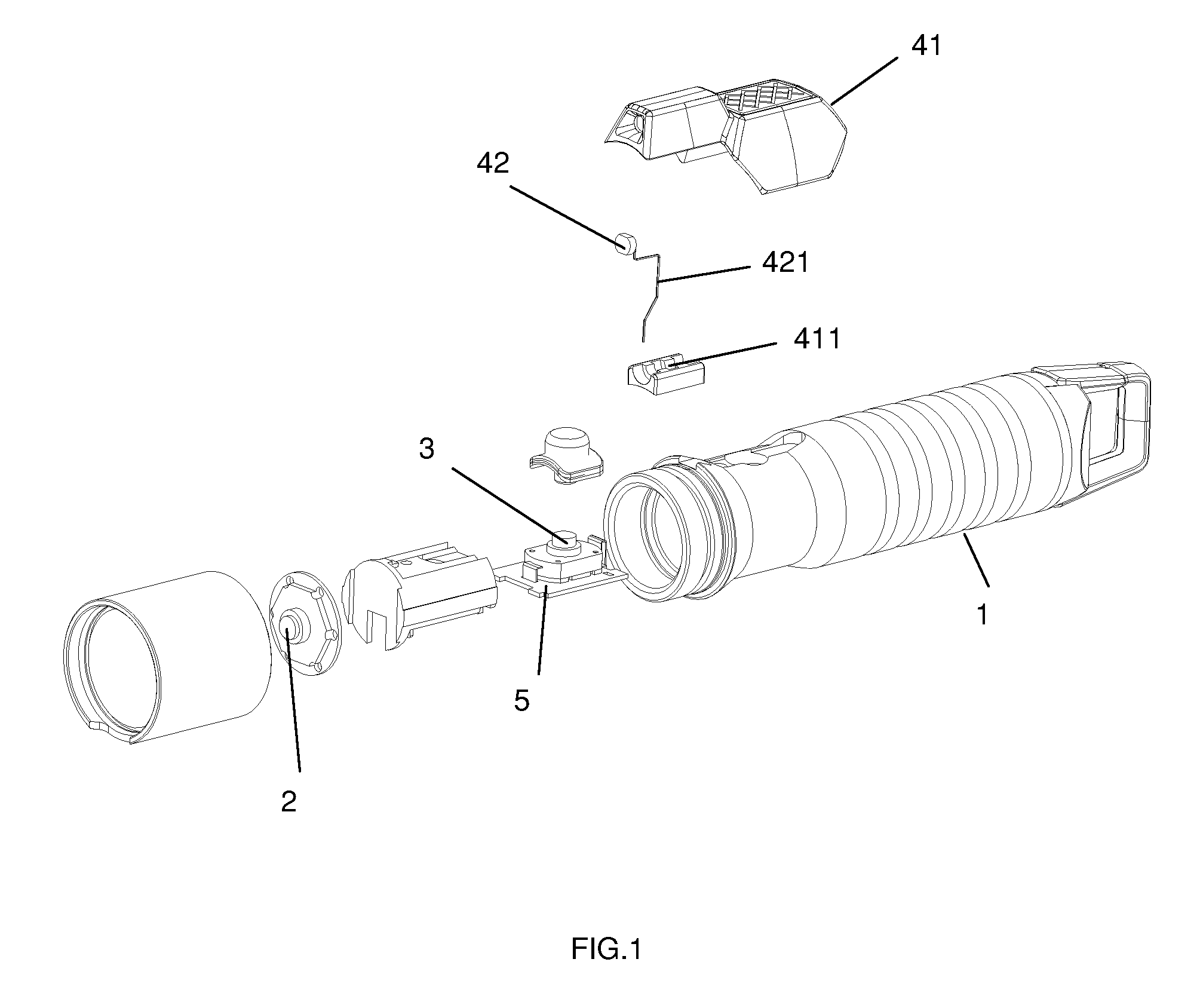
A flashlight with automatic light intensity adjustment means comprising a flashlight casing, a light source, a switch, a light controlling circuit on a printed circuit board and a power source, wherein a sensor component is attached to the flashlight casing, and the sensor component comprises a sensor casing and an incident light intensity sensor disposed therein, and the sensor is electronically connected to the light source, the switch, the light controlling circuit and the power source, and the light controlling circuit controls electrical current passing through the light source according to intensity of incident light as detected by the sensor so that more current is passed through the light source when a lower intensity of incident light is detected, and less current is passed through the light source when a higher intensity of incident light is detected.

Description

BACKGROUND OF THE INVENTION[0001]The present invention relates to a flashlight with automatic light intensity adjustment means and more particularly pertains to a flashlight capable of automatically adjusting the light intensity according to the intensity of incident light reflected from the nearest object facing the light source of the flashlight.[0002]Flashlights are indispensable for household use. For example, when there is an outage of electricity, it is necessary to use flashlight to light the way. In some instances when household hardware which is located in relatively dark corners of the house, such as fuse box and pipelines, is damaged, it is also necessary to use flashlight to light the dark corners to repair the damaged hardware.[0003]Flashlights are also indispensable for various outdoor activities such as camping and mountain climbing. Especially in countryside where public lighting facilities and installations are rare, it is essential for people to use their own flash...

Claims


Application Information

Patent Timeline
IPC IPC(8): F21V33/00
CPCF21L4/005F21V23/0442H05B33/0854H05B33/0803F21Y2101/02F21Y2115/10H05B45/00H05B45/345H05B45/12
Inventor MAN, SHIU-FAI STEPHEN
Owner KAPER INDAL
Learn More