
Fluid mixing device

a technology of mixing device and flue, which is applied in the direction of fuel supply apparatus, combustion process, secondary air addition to fuel, etc., can solve the problems that the actual local flame speed is still limited by the laminar flame speed, and the limit factor in flame stability is the propagation speed of the flame front, so as to increase the probability of flame extinguishing

Inactive Publication Date: 2008-08-12
LUMINIS PTY LTD
View PDF35 Cites 10 Cited by
  • Summary
  • Abstract
  • Description
  • Claims
  • Application Information

AI Technical Summary

Benefits of technology

[0006]In other preferred configurations it is an object to provide a burner that will provide a stable and continuous flame while being subjected to winds or draughts of widely variable direction and speed.
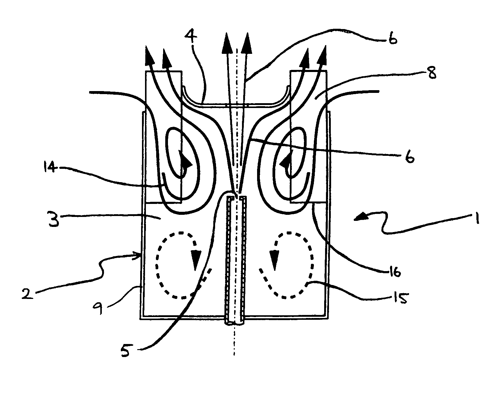
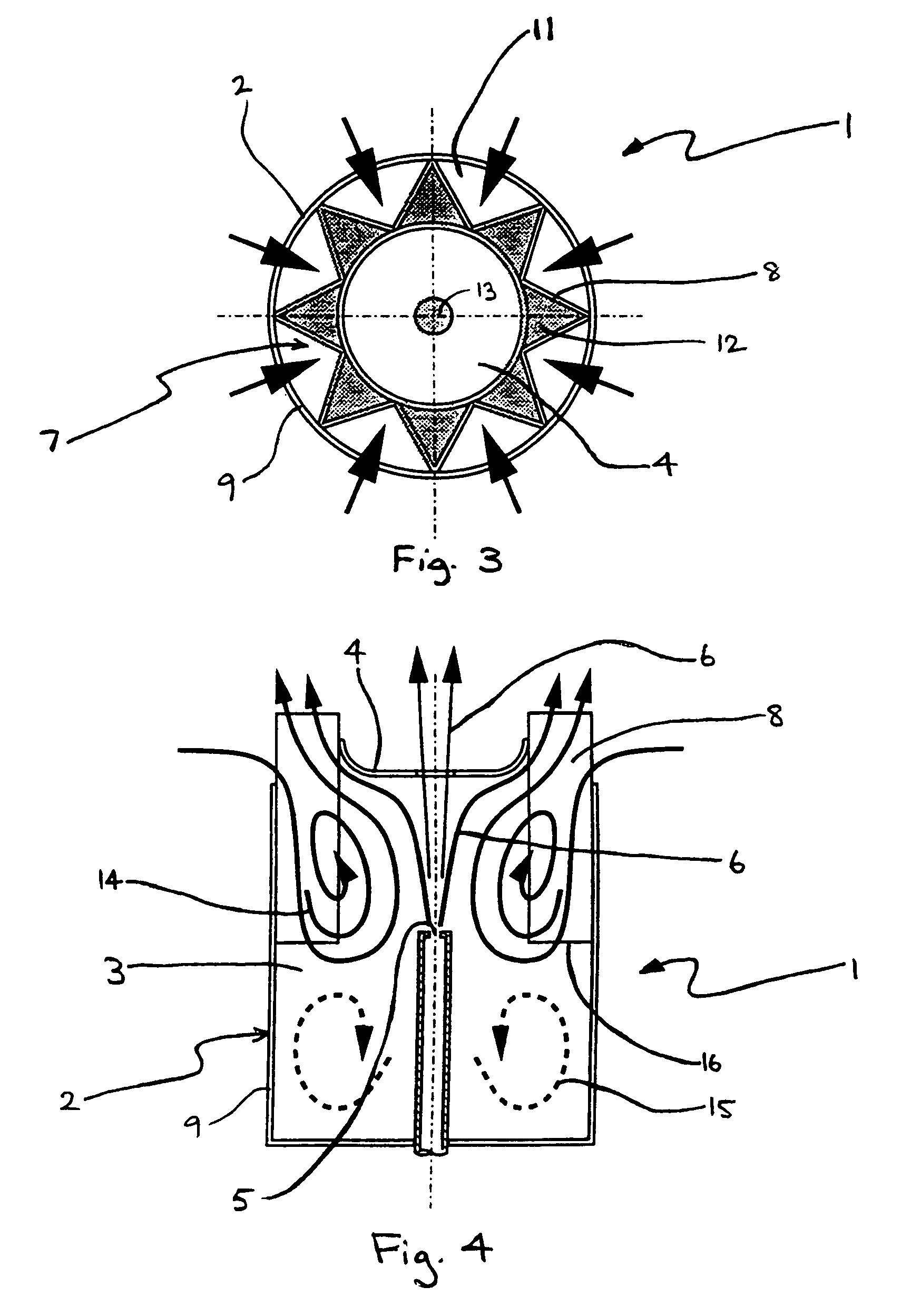
[0013]The structure of the device according to this invention provides an arrangement which will shield an internal flame from high velocity external cross winds and further ensures that the flow velocity within the chamber is kept below the values required to extinguish combustion. This is achieved by the device producing a self stabilising flow pattern which is independent of the wind direction and speed. The independence from cross-wind speed and direction requires that only one dominant flow pattern be established independent of external flow direction and speed. The geometry defined in the invention prevents the flow from “switching” between one vortex flow pattern and another as the cross-wind speed and direction changes. “Switching” is undesirable because in the brief time between the cessation of one stabilising flow pattern and the establishment of another, no flame stabilising mechanism will exist. Thus switching greatly increases the probability that the flame may be extinguished. In accordance with the preferred form of the present invention the flow of external air into the chamber and the flow of fluid out of the chamber can be controlled in order to optimise mixing between the air and the fuel and thus maintain continuous and stable combustion within the chamber.
[0016]In accordance with preferred features of the burner embodiment the following modifications can enhance control of flow entering the chamber and control of flow within the chamber:
[0019](3) the bluff body may be shaped with a curve at its outer edge to provide less resistance to the flow through the mixed fluid outlets;
[0020](4) the chamber wall may be bell mouthed, curved, or bevelled outwardly at the second fluid inlets to provide less resistance to flow through those inlets to the chamber;

Problems solved by technology

A limiting factor in flame stability is the propagation speed of the flame front.
Although it is possible to produce stable flames in turbulent flows where the mean flow speed is an order of magnitude higher than the laminar flame speed, the actual local flame speed is still limited by the laminar flame speed.

Method used


Image

  • Fluid mixing device
  • Fluid mixing device
  • Fluid mixing device

Examples


Embodiment Construction

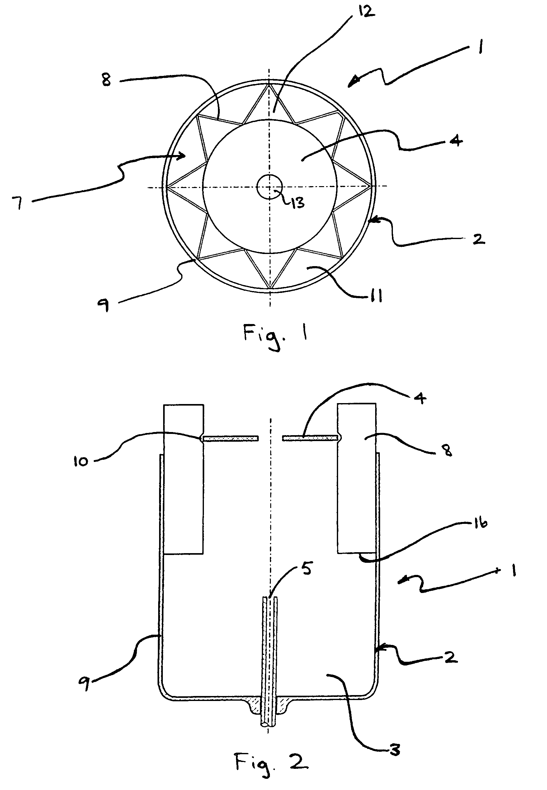
[0045]FIGS. 1 to 4 show a mixing device 1 according to this invention configured to operate as a burner using a mixture of 35% propane and 65% butane gaseous fuel. The fluid mixing device 1 includes a cup 2 which forms a chamber 3 closed at one end by a bluff body 4. A first fluid inlet, referred to as a jet inlet 5, extends from one end of the cup 2 and is arranged to direct a gas flow 6 toward the bluff body 4. An annular region 7 surrounding the bluff body 4 includes a corrugated flow divider 8 of triangular profile. The flow divider is supported by being fixed to the cup wall 9 and extends from within chamber 3 to beyond bluff body 4. As best seen in FIG. 2 the bluff body 4 is positioned beyond the end of cup 2 by retaining notches 10 formed in the flow divider 8. Due to its corrugated profile flow divider 8 repeatedly crosses annular region 7 between bluff body 4 and cup wall 9 which extends around the perimeter of annular region 7. In this way flow divider 8 defines a series o...


PUM

PropertyMeasurementUnit
speedaaaaaaaaaa
speedsaaaaaaaaaa
speedsaaaaaaaaaa

Abstract

A fluid mixing device (1) includes a chamber (3) and a bluff body (4) defining one end of the chamber (3). A first fluid inlet (5) is located toward an opposite end of the chamber (3) from the bluff body (4) and arranged to direct fluid toward the bluff body (4). A region substantially surrounding the bluff body (4) has a flow divider (8) defining second fluid inlet(s) (11) to the chamber (3) and mixed fluid outlets (12) from the chamber (3). A fluid flow from the first fluid inlet (5) and / or from the second fluid inlet (11) establishes a recirculating vortex system (14) within the chamber and results in a mixture of fluids from the first fluid inlet (5) and the second fluid inlet(s) (11) being directed through the mixed fluid outlets (12).

Description

FIELD OF THE INVENTION[0001]This invention relates to fluid mixing devices and in particular to such devices which mix one fluid with another fluid that may be flowing with widely variable direction and speed. In the following description the invention will primarily be described with reference to burner applications in which a combustible fluid (or fuel) is mixed with air to produce a flammable mixture. The invention is however not limited to this application and can be used in a wide variety of fluid mixing devices particularly where one of the fluids is flowing and a second fluid is required to be mixed with the flowing fluid in a relatively stable manner.BACKGROUND ART[0002]Numerous applications exist in which a burner is required to provide a stable flame while being subjected to winds or draughts of widely variable direction and speed, and under highly turbulent, or gusting conditions. Examples include flares, camping stoves, ceremonial torches and pilot burners in boilers and...

Claims


Application Information

Patent Timeline
Patent Type & Authority Patents(United States)
IPC IPC(8): F23C7/00B01F23/00F23D14/64
CPCB01F5/0475F23D14/64B01F2215/0085B01F25/3142B01F2101/501
Inventor KELSO, RICHARD MALCOLMLANSPEARY, PETER VERNONNATHAN, GRAHAM J.HILL, STEVEN J.PARHAM, JORDAN JAMESKELLY, GRAHAMCUTLER, PHILIP ROBERT EDWARDBUDRULHISHAM, MOOHD GHAZALI
Owner LUMINIS PTY LTD
Learn More