Method and apparatus for radio frequency cavity

a radio frequency cavity and apparatus technology, applied in the direction of instruments, mass spectroscopy, beam deviation/focusing by electric/magnetic means, etc., can solve the problems of significant thermal engineering problems, detrimental changes in rf properties and beam quality, accelerator housing, etc., to prevent the breakdown of the microwave field

Active Publication Date: 2008-08-12
RADIABEAM TECH
View PDF24 Cites 12 Cited by
  • Summary
  • Abstract
  • Description
  • Claims
  • Application Information

AI Technical Summary

Benefits of technology

[0014]In a further aspect, the walls of the flow path have a surface roughness (Ra) of between 800 to 1200 micro inches in order to cause turbulent flow of the cooling fluid in the channel, thereby increasing the heat conduction from the housing.
[0016]In a final aspect, the surface that is exposed to the radiofrequency field is subjected to processing after fabrication in order to achieve surface roughness of less than 63 micro inches. Such a surface is advantageous in order to prevent breakdown of the microwave field.

Problems solved by technology

The key issue for high average power, normal conducting, photo-injectors and RF accelerating structures is to effectively cool the housing structure.
This heating presents significant thermal engineering problems.
The large amount of power dissipated in the structure can cause “hot spots” and local thermo-mechanical distortions which may lead to detrimental changes in RF properties and beam quality.
One of the most challenging parts of an accelerator housing to be cooled are the “irises” which protrude into the cavity of the housing.
Another challenging aspect to be cooled is the so-called RF coupler, which is a thin walled interface between the waveguide and the cavity.
Accordingly, the problem of thermal gain has been approached by providing channels within the housing structure, and forcing water to flow through the channels in combination with cooling the water on the outside of the housing by conventional heat dissipation means such as by radiator.
However, the prior art is limited in the method for creating, and configuring the channels used for cooling the housing structure.
It will be understood that this kind of configuration greatly limits the cooling uniformity and rate of cooling in that fluid flow is dramatically slowed by the sharp changes in direction (discontinuities in flow gradient), thereby reducing the rate at which heat can be extracted.
However, brazing multiple components to form high gradient RF structures is a delicate and expensive step, and many braze cycles are needed to build an effective cooling structure.
Moreover, the resulting structure is not uniform or homogeneous, which adversely affects the efficiency at which heat can be extracted from the housing by water in the channels.

Method used


Image

  • Method and apparatus for radio frequency cavity
  • Method and apparatus for radio frequency cavity
  • Method and apparatus for radio frequency cavity

Examples


Embodiment Construction

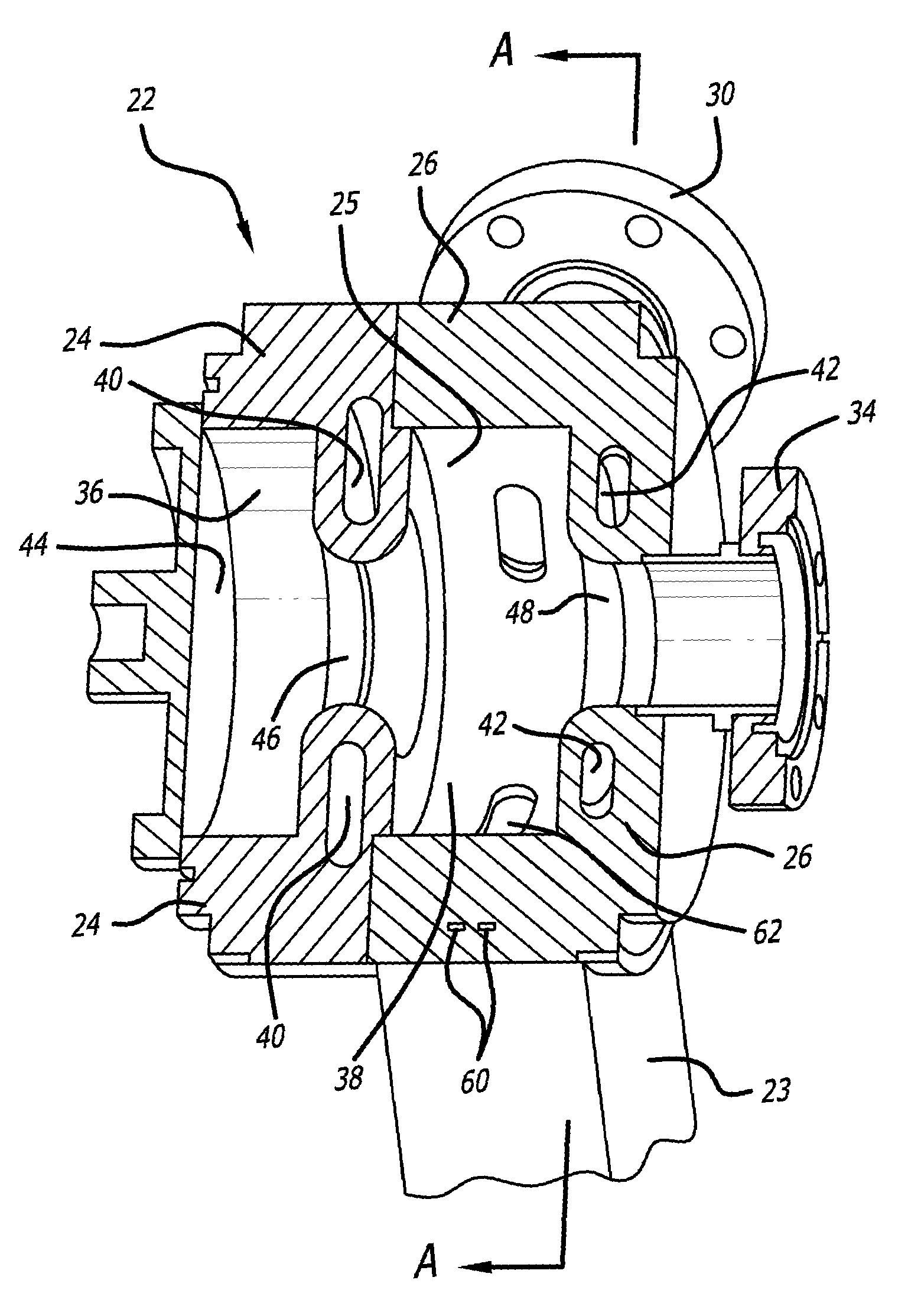
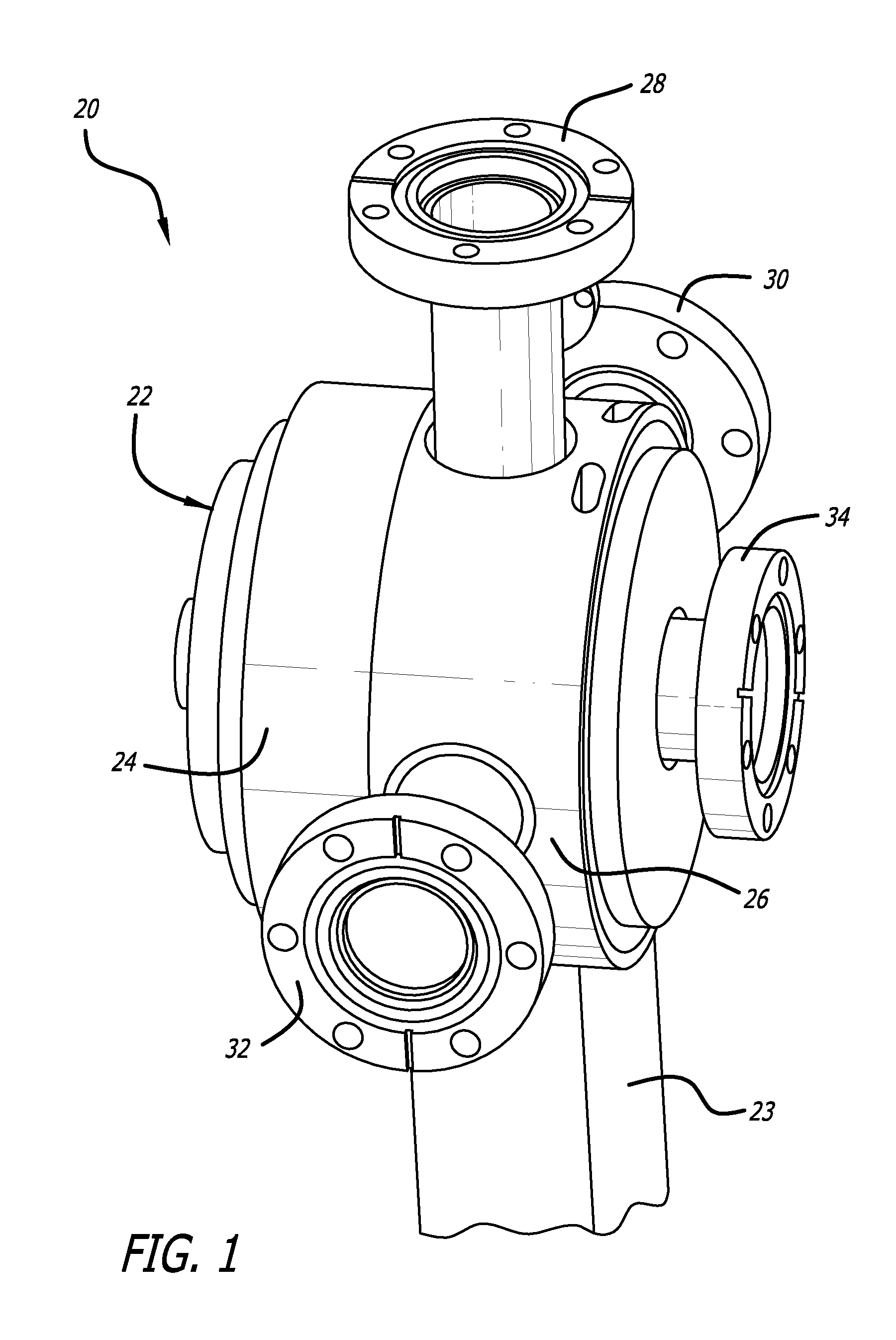
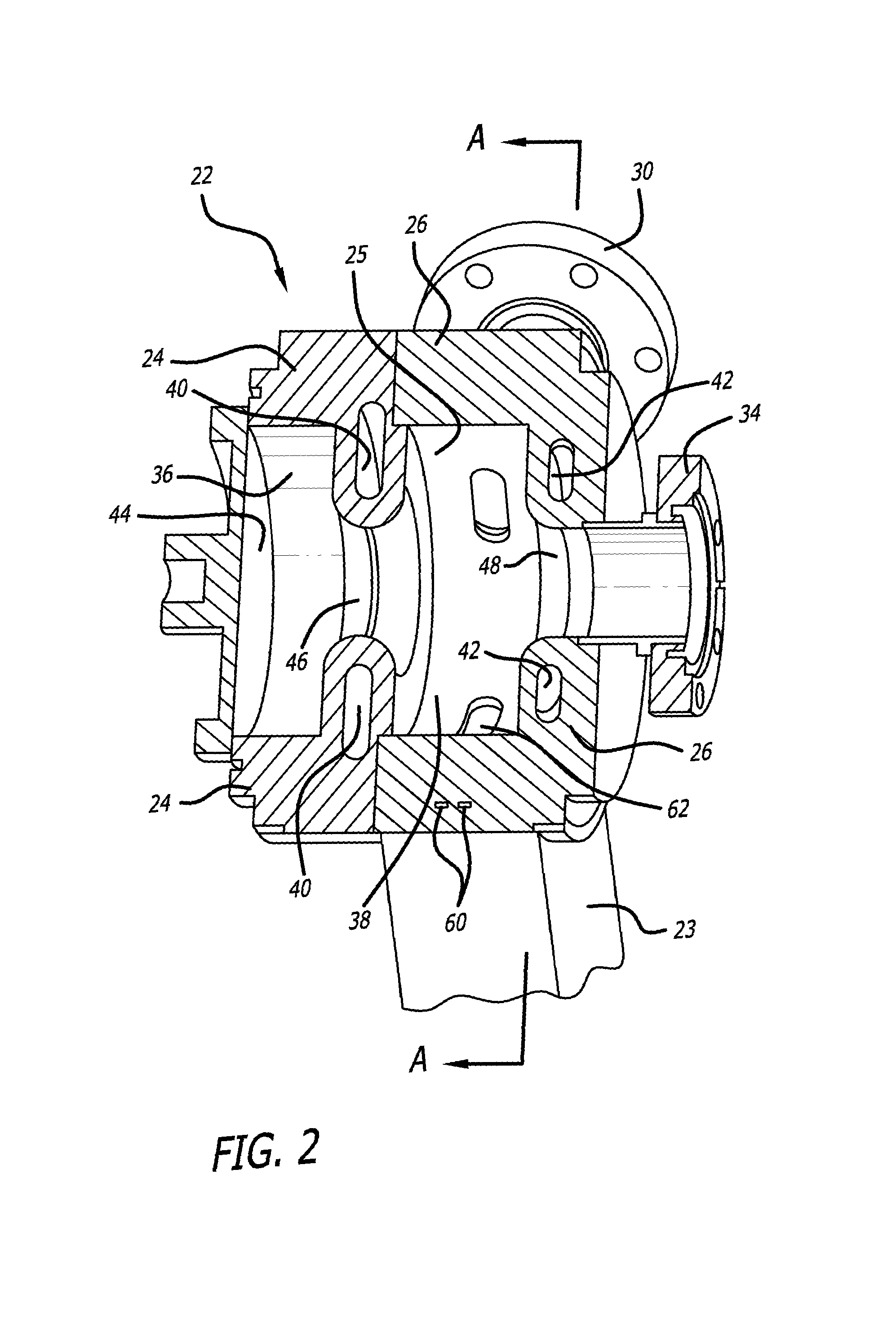
[0023]With reference to the drawings, which are provided by way of exemplification and not limitation, preferred embodiments of the invention are described below. Prior to describing the embodiments of the invention, however, known technology used in effectuating the invention will be described.

[0024]Turning now to a method of effectuating the present invention, a method of constructing a housing for an RF accelerator will be described that is capable of manufacturing structure capable of overcoming the shortcomings of the prior art. Metal additive fabrication technologies, such as Electron Beam Melting (EBM), have been described for example in U.S. Pat. No. 5,786,562 (Larson), U.S. Pat. No. 6,112,804 (Sachs et al.), U.S. Pat. No. 6,391,251 (Keicher et al.), U.S. Pat. No. 6,401,001 (Jang et al.). The contents of each of these patents is incorporated herein by reference. These technologies employ rapid prototyping layer methods to allow for virtually any three dimensional geometry to...


PUM


Abstract

In an electron accelerator, a conductive housing defines a cavity. Photoelectrons are emitted from a photocathode into the cavity when light is applied to the photocathode. Via an opening formed in a wall of the conductive housing, the photoelectrons are output to the outside of the cavity. Coolant is flowed through a flow path formed in the wall of the conductive housing, to suppress a temperature rise of the conductive housing. The wall of the conductive housing is made by a metal additive manufacturing technique in such a way as to produce a flow path that has a gentle trajectory without discontinuities in gradient.

Description

BACKGROUND OF THE INVENTION[0001]The present invention relates to a particle accelerating structure, and more particularly to a structure suitable for both increasing the energy of and raising a repetition frequency of a particle beam periodically emitted from the structure. The particle stream emitting from an RF accelerating structure may be used for multiple purposes, for example medical treatment, non-destructive investigation of solid objects, and the like.[0002]An example of a particle accelerator suitable for application of the present invention is a radio-frequency (“RF”) accelerator using a photocathode which typically comprises a conductive housing defining a cavity, a photocathode for emitting photoelectron into the cavity, and a wave guide for generating an RF electric field in the cavity. As light is periodically applied to the photocathode, photoelectrons are emitted into the cavity intermittently. These photoelectrons are converged and accelerated by an RF electric fi...

Claims


Application Information

Patent Timeline
Patent Type & Authority Patents(United States)
IPC IPC(8): H05H9/00G21K1/08
CPCH01J23/005B33Y80/00
Inventor AGUSTSSON, RONALD B.BOUCHER, SALIME M.FRIGOLA, PEDRO E.MUROKH, ALEX Y.ROSENZWEIG, JAMES B.TRAVISH, GIL
Owner RADIABEAM TECH
Why Eureka
Try Eureka