Multilayer optic device and system and method for making same

a multi-layer optic and optical device technology, applied in the field of optics, can solve the problems of low diffracting volume, high false positive rate of edxrd, and low detection accuracy,

Active Publication Date: 2008-08-12
GENERAL ELECTRIC CO
View PDF5 Cites 53 Cited by
  • Summary
  • Abstract
  • Description
  • Claims
  • Application Information

AI Technical Summary

Problems solved by technology

Such EDXRD may suffer from high false positives due to weak diffracted X-ray signals.
Third, some of the materials being searched for, e.g., explosives, may not diffract strongly as they are amorphous.
Fourth, the diffracting volume may be small.
The last two limitations arise from the type of threat materials being searched for in baggage, making all but the second limitation unavoidable.
These types of optics typically do not provide much gain at energy levels above 80 keV, since the difference in the indices of refraction between air and glass becomes increasingly small as energy levels approach and surpass 80 keV.
Thus, known optics are limited in their potential uses.

Method used


Image

  • Multilayer optic device and system and method for making same
  • Multilayer optic device and system and method for making same
  • Multilayer optic device and system and method for making same

Examples


Embodiment Construction

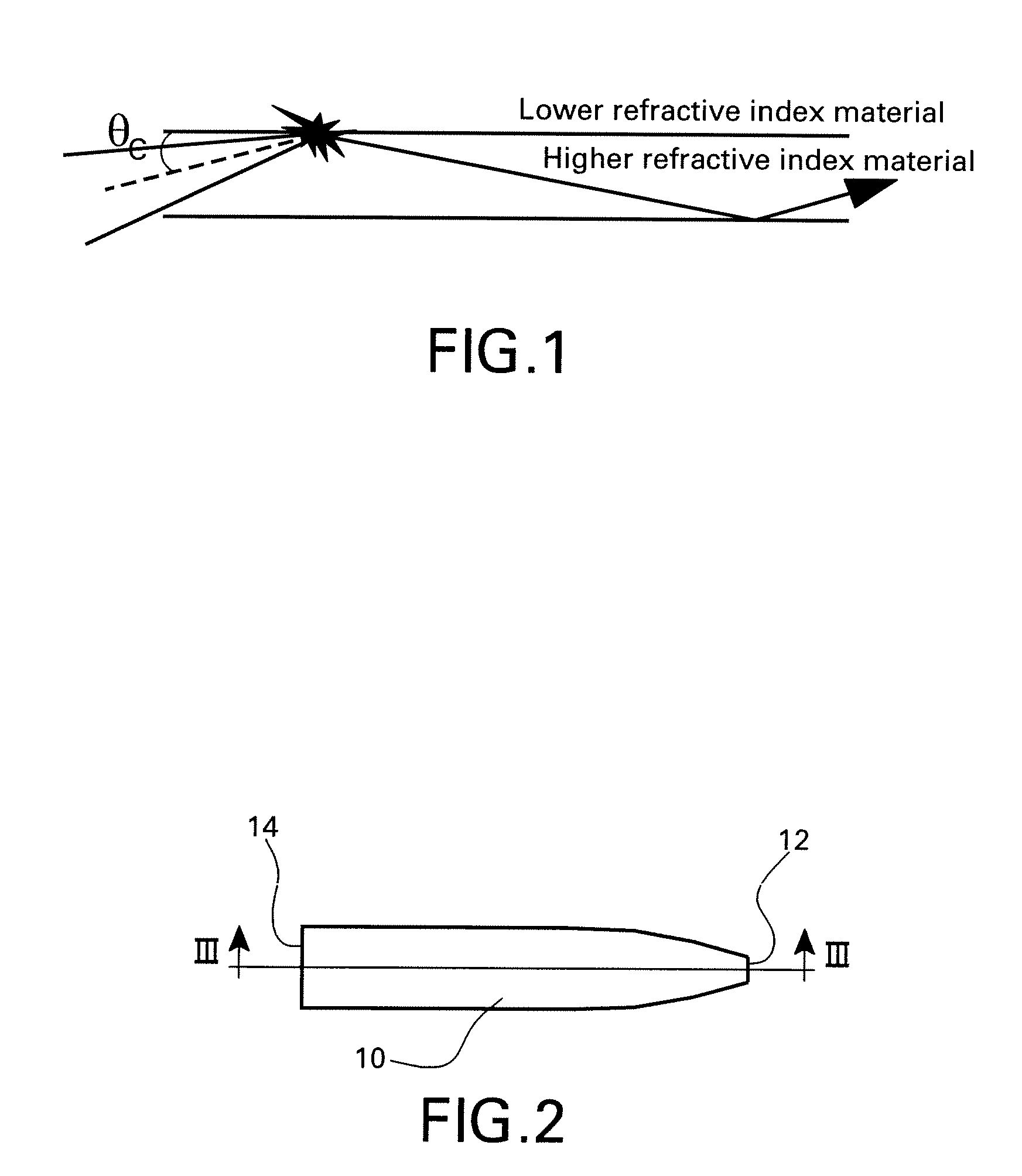
[0027]Embodiments of the invention described herein utilize the phenomenon of total internal reflection. Referring to FIG. 1, when an angle of incidence is less than a critical angle θc, total internal reflection occurs. The critical angle θc for total internal reflection depends on, among other factors, the material, the difference in the relative indices of refraction, and the energy of the incident photons.

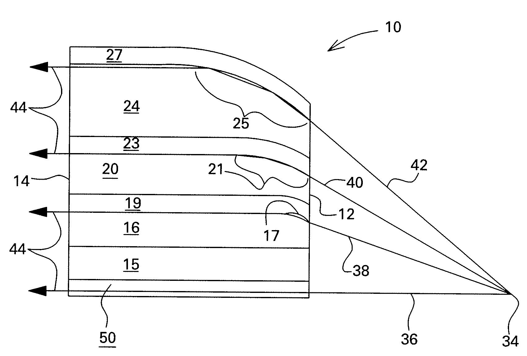
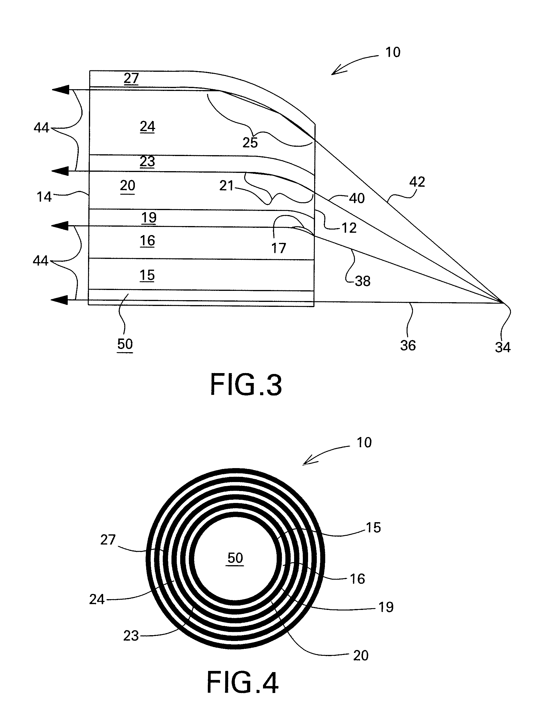
[0028]Referring now to FIGS. 2-5, there is shown a multilayer optic 10 including an input face 12 and an output face 14. By “multilayer” is meant a structure that has a plurality of monolayers. As shown more particularly in FIGS. 3 and 4, the multilayer optic 10 includes multiple layers of material, each having a different index of refraction. For example, there are layers 16, 20, and 24 surrounding a core 50. Layer 16 is positioned radially exterior to and contiguous with the core 50. The core 50 may be formed of a higher index of refraction material such as beryllium, lithium...


PUM


Abstract

An optic device, system and method for making are described. The optic device includes a first solid phase layer having a first index of refraction with a first photon transmission property and a second solid phase layer having a second index of refraction with a second photon transmission property. The first and second layers are conformal to each other. The optic device may be fabricated by vapor depositing a first layer and then vapor depositing a second layer thereupon. The first layer may be deposited onto a blank or substrate. The blank or substrate may be rotated during deposition. Further, a computer-controlled shutter may be used to alter the deposition rate of material along an axis of the optic device. Alternatively, the optic device may be moved at varying speeds through a vapor stream to alter the deposition rate of material.

Description

BACKGROUND[0001]The invention relates generally to optics, and more particularly to multilayer optic devices and methods for making the same.[0002]Numerous applications exist that require a focused beam of electromagnetic radiation. For example, energy dispersive X-ray diffraction (EDXRD) may be used to inspect checked airline baggage for the detection of explosive threats or other contraband. Such EDXRD may suffer from high false positives due to weak diffracted X-ray signals. The weakness of the X-ray signals may stem from a variety of origins. First, the polychromatic X-ray spectrum used in EDXRD is produced by the Bremsstrahlung part of the source spectrum, which is inherently low in intensity. Second, X-ray source may collimation eliminate more than 99.99 percent of the source X-rays incident on the baggage volume under analysis. Third, some of the materials being searched for, e.g., explosives, may not diffract strongly as they are amorphous. Fourth, the diffracting volume may...

Claims


Application Information

Patent Timeline
Patent Type & Authority Patents(United States)
IPC IPC(8): G02B6/42
CPCG21K1/06
Inventor LEE, SUSANNE MADELINEHOPKINS, FORREST FRANK
Owner GENERAL ELECTRIC CO
Why Eureka
Try Eureka