Engine control device

a control device and engine technology, applied in the direction of electric control, engine starters, machines/engines, etc., can solve the problems of increasing the power consumption of batteries, reducing the startability of engines, and reducing the accuracy of engine cranking, etc., to achieve high accuracy

Active Publication Date: 2008-08-19
MAHLE INT GMBH
View PDF15 Cites 8 Cited by
  • Summary
  • Abstract
  • Description
  • Claims
  • Application Information

AI Technical Summary

Benefits of technology

[0016]An object of the present invention is to provide an engine control device that prevents a shortage in fuel injection amount at the start of an engine to improve startability of the engine, and reduce an exhaust amount of unburned gas to improve an exhaust gas characteristic at the start of the engine.
[0019]As described above, if the first fuel injection is performed after the completion of the first driving of the fuel pump and before the driving of the starter motor, the first fuel injection can be performed with stable fuel pressure supplied to the injector and a stable driving voltage of the injector (before a power supply voltage is reduced by the driving of the starter motor), thereby allowing the fuel to be injected in an amount as arithmetically operated at the time of the first fuel injection. This prevents a shortage in fuel injection amount at the start of the engine to improve startability of the engine. The shortage in the fuel injection amount can be prevented at the start of the engine to prevent failure in ignition at the time of first ignition, thereby reducing an exhaust amount of unburned gas to improve an exhaust gas characteristic at the start of the engine.
[0022]In the case where the starter generator is used as described above, the engine control device includes: first fuel pump driving means for driving the fuel pump only during set time at power-on of the microprocessor; first fuel injection control means for causing the injector to perform first fuel injection when it is confirmed that the driving of the fuel pump by the first fuel pump driving means is completed and that a start command for commanding the start of the engine is given; starter control means for controlling the starter generator so as to cause the starter generator to function as the starter motor to start the engine when it is confirmed that the first fuel injection is completed and that the start command is given; and generation output control means for controlling a generation output of the starter generator so as to prevent a voltage across the battery from exceeding a set value when the start of the engine is confirmed.
[0025]The controls are thus shared by the two microprocessors to reduce the number of the control items for each microprocessor, thereby allowing control of the fuel injection amount and control of the generation output to be performed with high accuracy.

Problems solved by technology

In the conventional control device, crank angle information of the engine is obtained from an output of a crank angle sensor mounted to the engine, and first fuel injection is performed when the fuel injection timing is detected based on the crank angle information, thereby inevitably causing a delay between the start of the cranking of the engine and the first fuel injection.
If the first fuel injection delays, an air / fuel ratio of an air / fuel mixture supplied into a combustion chamber of the engine reaches a predetermined value with a delay, thereby reducing startability of the engine.
Poor startability of the engine increases time for driving a starter motor to increase power consumption of a battery, which requires a high capacity battery and is uneconomical.
When the battery voltage decreases, a driving voltage of the injector decreases, and thus a valve of the injector is opened with a delay to prevent a desired amount of fuel from being injected from the injector.
The injector does not open the valve immediately after a driving voltage is supplied, but there is delay time (referred to as ineffective injection time) between when the driving voltage is supplied and when the valve is actually opened.
As shown in FIG. 10, the ineffective injection time is increased with decreasing injector driving voltage.
Thus, as shown in FIG. 11, if the battery voltage decreases at the start of the engine to reduce the injector driving voltage, the ineffective injection time of the injector is increased to delay opening of the valve of the injector.
The delay of the opening of the valve of the injector causes a shortage in fuel injection amount even if the fuel pressure supplied to the injector is sufficiently increased, thereby inevitably reducing startability of the engine.
However, at the start of the engine, changes in internal pressure of a cylinder caused by a stroke change of the engine cause a load applied to the starter motor to vary, and as indicated by the curve a in FIG. 11, the rotational speed finely changes according to crank angles, and the variation in the load causes the battery voltage to change.
As described above, the battery voltage significantly changes at the start of the engine, and thus it is difficult to detect the battery voltage to precisely arithmetically operate the ineffective injection time, and difficult to properly correct the ineffective injection time relative to the battery voltage to control the fuel injection amount with high accuracy.
However, when the key switch is closed, the fuel pressure supplied to the injector is often insufficient.
If the fuel pressure supplied to the injector is insufficient when the key switch is closed, a desired amount of fuel cannot be injected even if first fuel is injected when the key switch is closed, thereby failing in ignition of the fuel at the time of first ignition thereafter, and inevitably reducing startability.
The failure in the ignition of the fuel causes unburned gas to be exhausted to pollute the atmosphere.
Further, if time is long between when the key switch is closed and when the starter switch is closed, the fuel injected by the injector adheres to an inner surface of an intake pipe or an inner surface of a cylinder to form a liquid film, which causes a shortage of fuel that contributes to combustion and reduce startability of the engine.
Also in this case, the failure in the ignition in the cylinder causes unburned gas to be exhausted to unpreferably pollute the atmosphere.

Method used


Image

  • Engine control device
  • Engine control device
  • Engine control device

Examples


Embodiment Construction

[0038]Now, a preferred embodiment of the present invention will be described in detail with reference to the drawings.

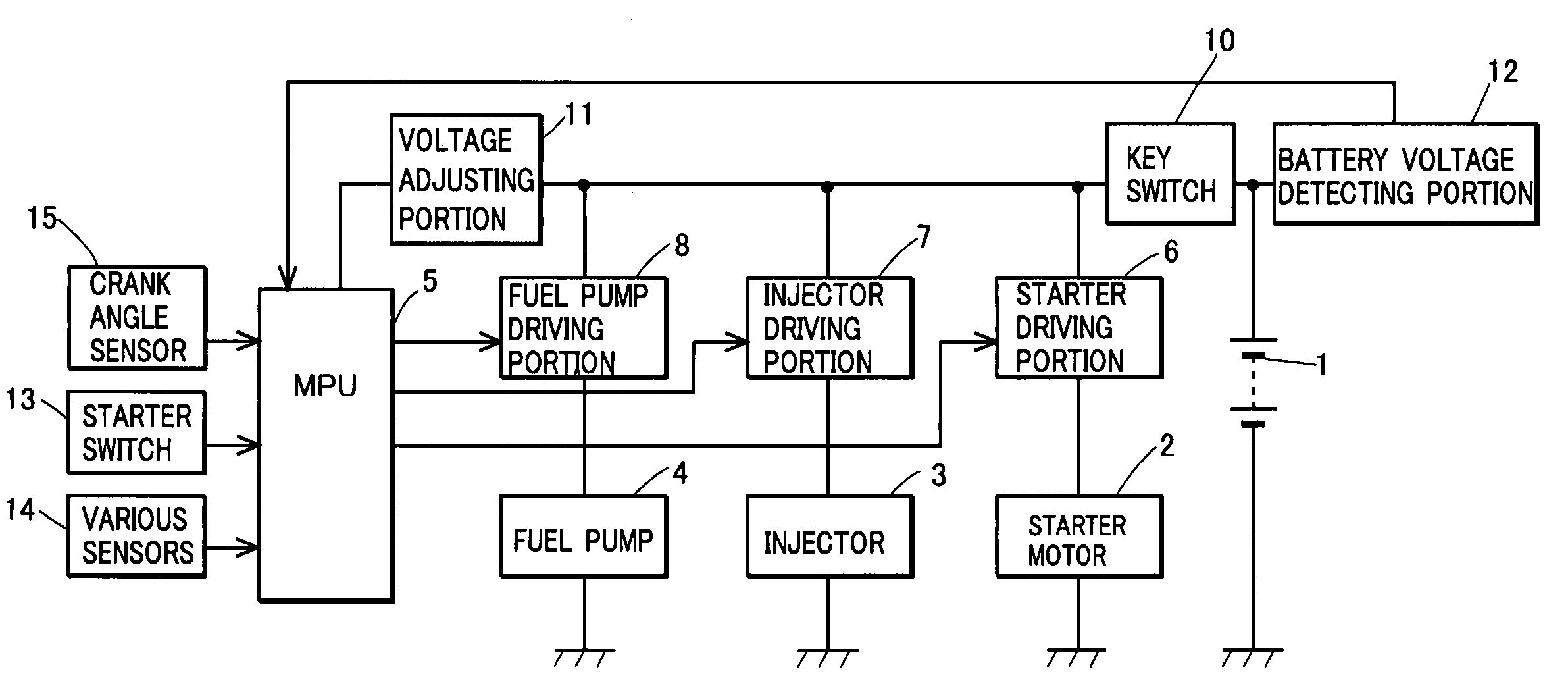
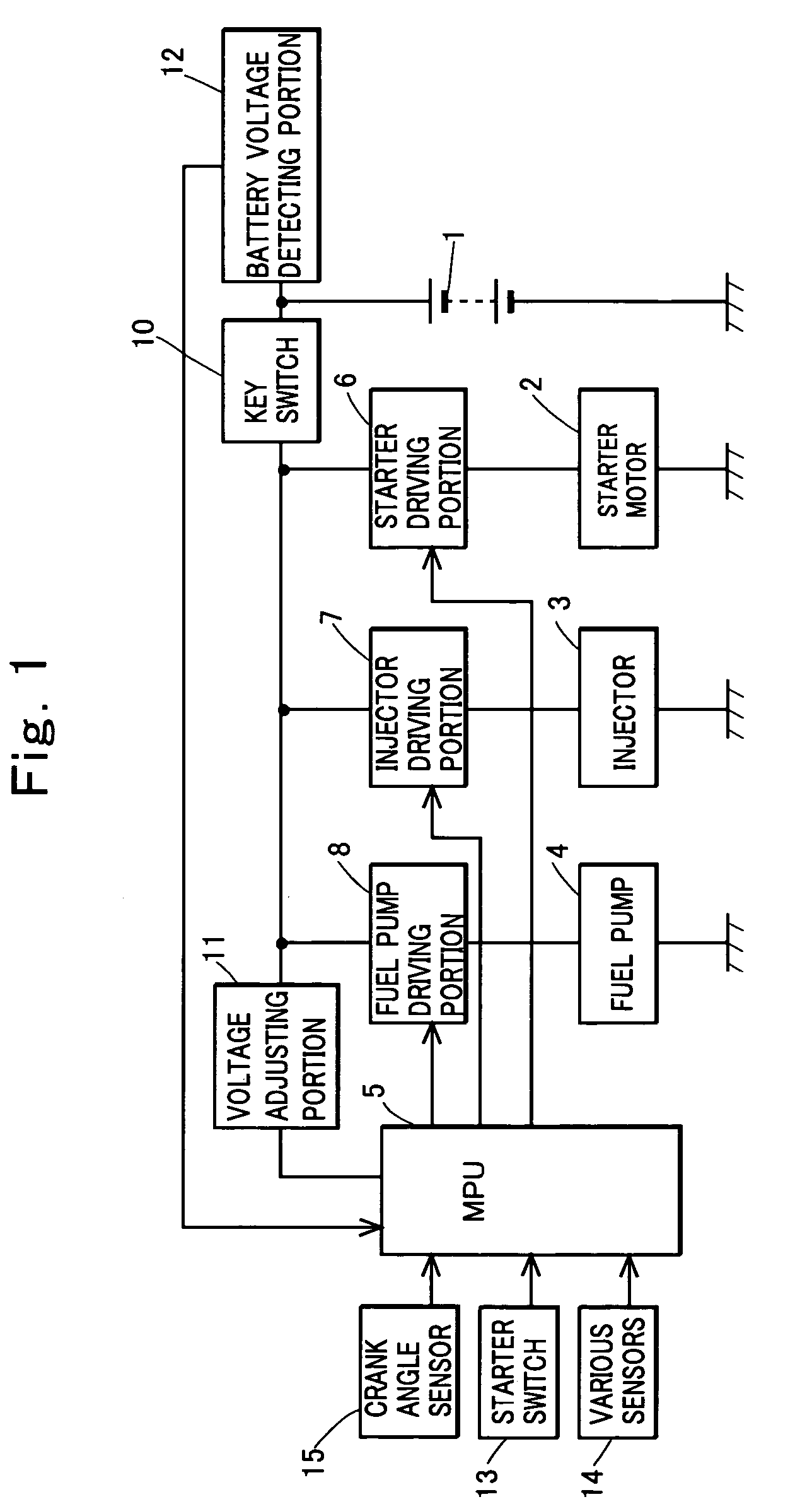
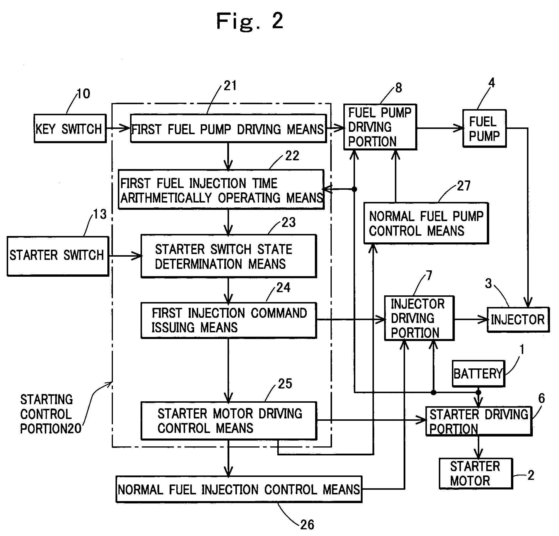
[0039]FIGS. 1 to 4 show a first embodiment of the present invention, FIG. 1 shows a construction of hardware, and FIG. 2 shows a construction of a control device including means realized by a microprocessor. FIG. 3 is a flowchart showing an algorithm of a program executed by the microprocessor for constructing the means in FIG. 2, and FIG. 4 is a timing chart showing operations at the start of the engine in the embodiment.

[0040]In FIG. 1, a reference numeral 1 denotes a battery; 2, a starter motor that starts an unshown engine; 3, an injector (an electromagnetic fuel injection valve) that injects fuel to be supplied to the unshown engine; 4, a fuel pump that pumps up fuel in an unshown fuel tank and supplies the fuel to the injector 3; and 5, a microprocessor that receives a power supply voltage from the battery 1 and is operated. A starter driving portion 6 is provi...


PUM


Abstract

An engine control device that controls, using a microprocessor, a fuel injection device including an injector and a fuel pump, and a starter motor that starts an engine, including: first fuel pump driving means for driving the fuel pump only during set time at power-on of the microprocessor; and first fuel injection control means for causing the injector to perform first fuel injection before driving of the starter motor when it is confirmed that the driving of the fuel pump by the first fuel pump driving means is completed and that a start command for commanding the start of the engine is given.

Description

TECHNICAL FIELD OF THE INVENTION[0001]The present invention relates to an engine control device that controls a fuel injection device and a starter motor or a starter generator using a microprocessor.BACKGROUND OF THE INVENTION[0002]For an engine to which fuel is supplied by a fuel injection device, fuel needs to be supplied to an injector with sufficient pressure at the start of the engine in order to inject fuel in an amount required at the start of the engine to improve startability of the engine. Thus, as disclosed in Japanese Patent Laid-Open No. 2005-23911, a control device that controls an engine to which fuel is supplied by a fuel injection device includes means for first driving a fuel pump for a predetermined time when the control device is powered on, and the pressure of the fuel supplied to an injector is increased to a predetermined value before the start of cranking of the engine.[0003]When a starting device starts the cranking of the engine, the control device control...

Claims


Application Information

Patent Timeline
Patent Type & Authority Patents(United States)
IPC IPC(8): F02D41/06F02D29/06F02M37/04F02N11/04
CPCF02D41/062F02N11/04F02N11/08F02D41/266F02D41/406F02N99/006F02D2200/503
Inventor SHIMAZAKI, MITSUYOSHIKISHIBATA, KAZUYOSHISATO, HIROYASUKINOSHITA, TOMOHIRO
Owner MAHLE INT GMBH
Why Eureka
Try Eureka