
Electrochemical sensor with dry ionomer membrane and methodfor making the same

Inactive Publication Date: 2008-09-09
PERKINELMER HEALTH SCIENCES INC
View PDF24 Cites 5 Cited by
  • Summary
  • Abstract
  • Description
  • Claims
  • Application Information

AI Technical Summary

Benefits of technology

[0035]The invention is still further directed toward a sensor with increased consistenc

Problems solved by technology

The use of such solid, ionic conductive electrolyte elements in an electrochemical gas sensor has also been demonstrated, however, has not been heretofore proposed or used in such electrochemical gas sensors to solve the problems of electrode flooding in the typical prior art gas sensor, as we presently understand the prior art.
Solid-state gas sensors have demonstrated the advantage of being able to operate at elevated temperatures, however they have the disadvantages of slow response and recovery time and a high internal operating temperature.
The disadvantages and limitations of the state-of-the-art sensors prevent efficient usage of such sensors in battery-powered instruments.
Response time is relatively slow, and reproducibility between sensors and sensor cells is not high.
Also, they are relatively costly.
Unfortunately in the back side configuration the back side of the membrane is required to be free of liquid so that the sample gas can diffuse through the membrane to the sensing electrode.
Another concern of the state-of-the-art sensors is flooding of the electrode surfaces caused during the fabrication of the sensors.
Flooding causes the formation of liquid droplets on the electrode surface and results in decreased sensor sensitivity after assembly.
Electrochemical sensor arrangements where an electrode lies immediately adjacent to a hydrated ionomer membrane are prone to flooding.
The propensity to flood is further increased with the thickening of the electrode; hence thick film electrodes are more prone to flooding than thin film electrodes.
The use of wet Nafion® in the manufacturing process results in the formation of liquid droplets on the electrode; hence sensors are formed with decreased sensitivity.
Another problem associated with the use of wet Nafion® in electrochemical sensors is that wet parts are difficult to work with.
Therefore, making electrochemical sensors with dry Nafion® decreases the difficulty of handling materials during the manufacturing process.
Yet another problem associated with the use of wet Nafion® in the manufacturing of electrochemical sensors is that the wet parts may result in sensors with a varying amount of sensitivity from one another.

Method used


Image

  • Electrochemical sensor with dry ionomer membrane and methodfor making the same
  • Electrochemical sensor with dry ionomer membrane and methodfor making the same
  • Electrochemical sensor with dry ionomer membrane and methodfor making the same

Examples


Embodiment Construction

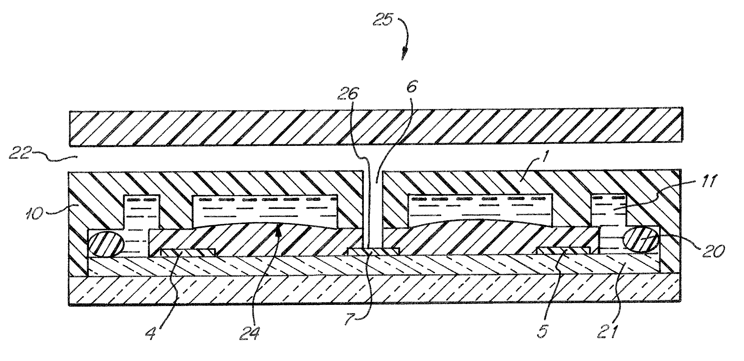
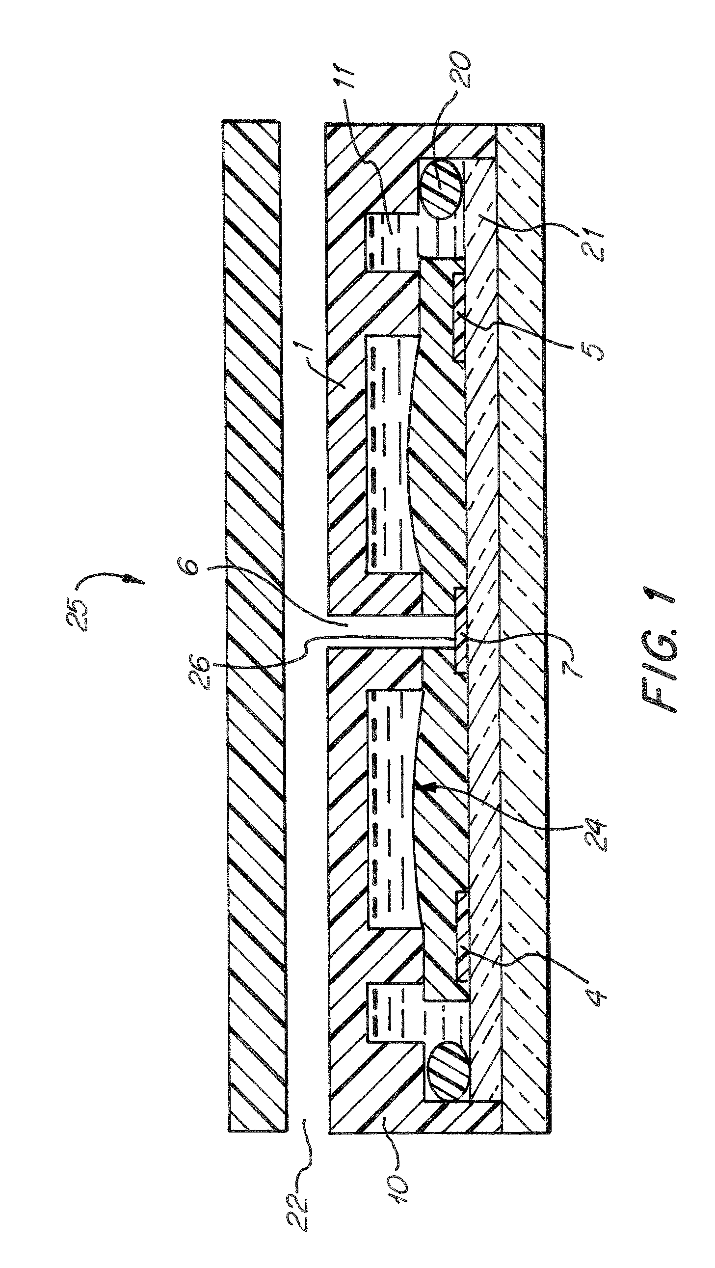
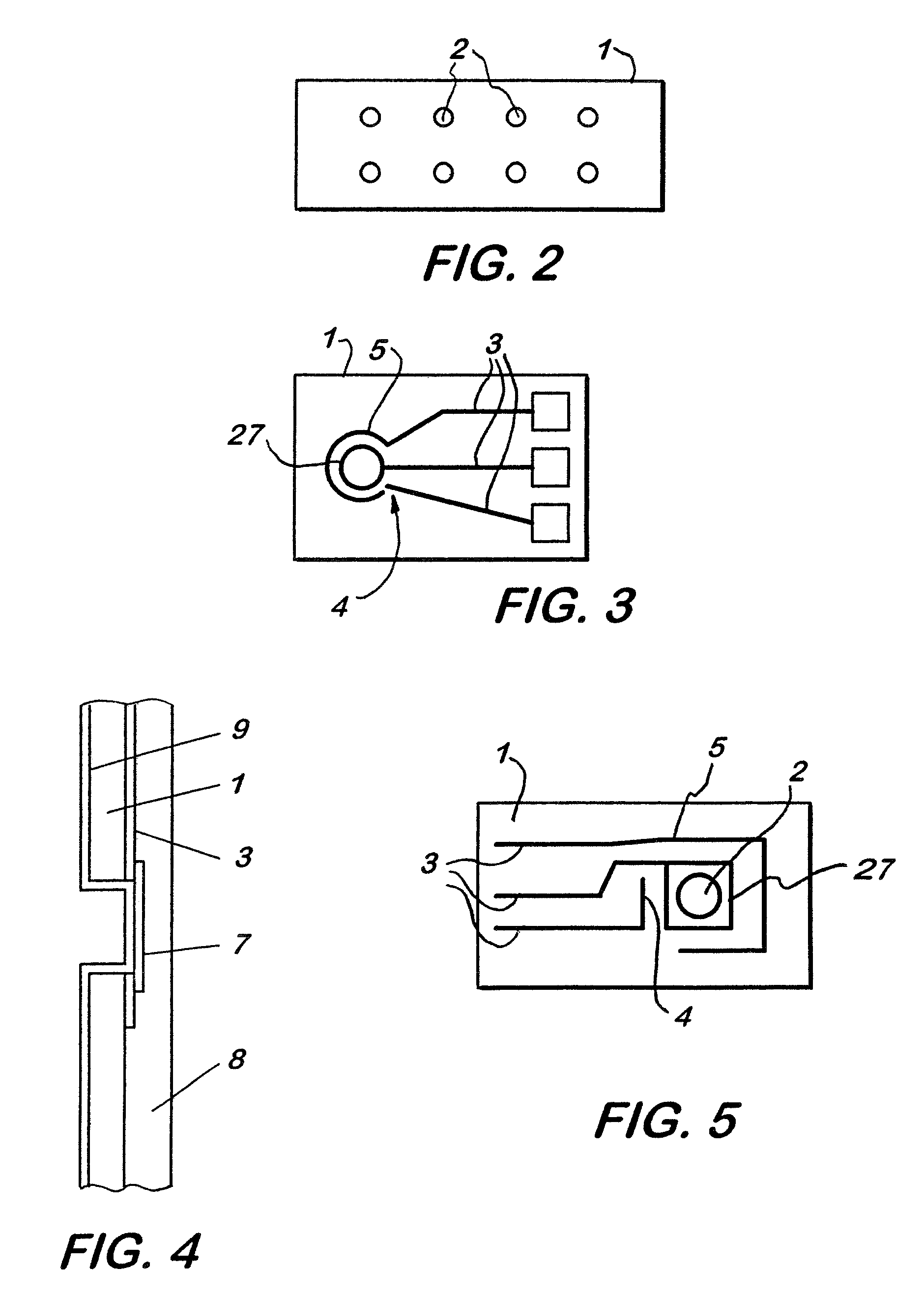
[0060]FIG. 1 shows a cross-sectional view of one preferred embodiment of the sensor cell assembly (25). The sensor housing (10) contains a substrate (1) and sensor chip (21). The sensor chip is incorporated into the substrate so that it acts as a natural extension of the substrate upon assembly. A reference electrode (4), a counter electrode (5), and a sensing electrode (7) are disposed on the sensor chip (21). An ionomer membrane (24), i.e. Nafion®117 about 0.183 mm. thick, is positioned upon the sensor chip (21) so that it is in contact with each electrode and the substrate (1). A three phase contact area (26) is formed by gas inlet (6), i.e. of a circular shape, about 1.0 mm in diameter through the substrate (1) and ionomer membrane (24) immediately adjacent the sensing electrode (7). When a sample gas enters the housing at gas entrance (22) it travels to gas inlet (6), in order to pass through the substrate (1) and ionomer membrane (24). At which point the gas can enter a three-...


PUM

PropertyMeasurementUnit
Fractionaaaaaaaaaa
Fractionaaaaaaaaaa
Fractionaaaaaaaaaa

Abstract

A miniaturized gas sensor comprised of film type electrodes, on a non-conductive supportive substrate, and in contact with a dry ionomer electrolyte, for detection of toxic gases, i.e., carbon monoxide, and other oxidizable or reducible gases and vapors and method of making same is described. The all-solid planar sensor cell has two or more film type electrodes arranged on a non-conductive planar surface of a supportive substrate. Manufacturing the electrochemical sensor with dry ionomer prevents electrode flooding and allows for improved response time upon assembly. The sensor cell contains no liquid electrolyte and is operated in a constant-voltage, potentiostatic or potentiodynamic mode. A high sensitivity to a select gas or vapor is achieved by a three-phase contact area design for a sensing electrode, which provides contact with the solid ionomer electrolyte, as well as the gas sample via diffusion openings or holes that penetrate through the supportive substrate.

Description

FIELD OF THE INVENTION[0001]The invention is directed toward an electrochemical sensor manufactured using a dry ionomer membrane, and a method of manufacturing the same.BACKGROUND OF THE INVENTION[0002]Solid, ionic conductive elements are known and have been used in hydrogen-oxygen fuel cells, as is well known to those skilled in the fuel cell art. The use of such solid, ionic conductive electrolyte elements in an electrochemical gas sensor has also been demonstrated, however, has not been heretofore proposed or used in such electrochemical gas sensors to solve the problems of electrode flooding in the typical prior art gas sensor, as we presently understand the prior art.[0003]The present invention provides an improved, less expensive and simpler construction for an electrochemical gas sensor as well as a simplified operation without the prior problems of flooding the electrodes caused by the use of wet ionomer membrane or resins during fabrication. The electrochemical gas-sensing ...

Claims


Application Information

Patent Timeline
IPC IPC(8): G01N27/407G01N27/49
CPCG01N27/4045G01N27/4071G01N27/401G01N27/40Y10T156/10Y10T29/49002G01N27/4074
Inventor PROHASKA, OTTO J.DALMIA, AVINASH
Owner PERKINELMER HEALTH SCIENCES INC
Learn More