Pneumatically static balancer for machine tool

a technology of pneumatically static balancer and machine tool, which is applied in the direction of machines/engines, manufacturing tools, fluid couplings, etc., can solve the problems of device expansion and inability to highly precisely position the driven member, and achieve the effect of eliminating the frictional resistance of the piston, high rigidity, and thin cylinders

Inactive Publication Date: 2008-09-16
KOMATSU NTC LTD
View PDF6 Cites 4 Cited by
  • Summary
  • Abstract
  • Description
  • Claims
  • Application Information

AI Technical Summary

Benefits of technology

[0013]Therefore, the invention has been conceived to solve those problems, and has an object to provide a pneumatically static balancer for a machine tool, in which a guide mechanism of a driven member to be moved by a vertical shaft is made into a static pressure bearing without enlarging the size of a device, which can be reliably moved even with an ultra-minute moving command of 0.1 μm by reducing the frictional resistance of a piston of the balancer substantially to zero and by minimizing the driving load resistance of the driven member, and which becomes a balance mechanism having high rigidity.
[0028]According to the first aspect of the invention, it is possible to provide a pneumatically static balancer for a machine tool, in which a static pressure bearing of a guide mechanism of a driven member to be moved by a vertical shaft can be made without enlarging the size of a device, in which the frictional resistance of a piston of a driven member balancer can be reduced substantially to zero, which can be reliably moved even with an ultra-minute moving command of 0.1 μm by minimizing the driving load resistance of the driven member, and which becomes a compact and highly rigid balance mechanism.
[0029]According to the second aspect of the invention, the leading end portion of the cylinder rod is supported by the spherical bearing so that the cylinder rod is supported by a low-resistance bearing such as a kind of universal joint. This makes it possible to absorb an eccentricity and a fine geometric distortion thereby to eliminate the frictional resistance of the piston.
[0030]According to the third aspect of the invention, the piston is provided with the plural air communication holes, and said piston is provided in its outer peripheral portion with the static pressure nozzles individually communicating with air communication holes. As a result, the cylinder can be made thin. Moreover, when the driven member descends, the cylinder internal pressure rises to enhance the air feed to the static pressure bearing thereby to improve the bearing effect and to ensure the non-contact stable balance support at all times. Moreover, the frictional resistance of the piston of the driven member balancer can be reduced substantially to zero to minimize the driving load resistance thereby to move the driven member reliably even with the ultra-minute moving command.
[0031]According to the fourth aspect of the invention, the piston is provided on the upper side and near the central portion thereof with a ring groove, which has an air exhaust passage for communicating the ring groove side with a lower face side of the piston, and the air exhaust passage is connected to a valve via a second hole formed on the lower face of the piston. As a result, it is possible to reduce the frictional resistance of the piston of the driven member balancer substantially to zero and to minimize the driving load resistance thereby to ensure the movement even with the ultra-minute moving command.
[0032]According to the fifth aspect of the invention, the piston is provided vertically in its outer peripheral surface with vertical grooves for communicating air, and lower ends of the vertical grooves do not reach to the lower end of the piston (that is, the lower end portions of the vertical grooves are formed into a not-go shape.) As a result, it is possible to reduce the frictional resistance of the piston of the driven member balancer substantially to zero and to minimize the driving load resistance thereby to ensure the movement even with the ultra-minute moving command.

Problems solved by technology

In case the driven member 102 is subjected to a slow or extremely minute feed, moreover, a stick slip phenomenon is caused due to the difference between a dynamic friction resistance and a static friction resistance to act between the piston of the hydraulic cylinder 111 and the outer cylinder of the hydraulic cylinder, thereby to raise a problem that the driven member cannot be highly precisely positioned.
However, because the above-described apparatus support the gravitational load by the air pressure fed to the one outlet closed chamber of the pneumatically static guide mechanism, a larger chamber than the driven member is required thereby to raise a problem that the device is enlarged (as referred to Japanese Patent Unexamined Publication No.

Method used


Image

  • Pneumatically static balancer for machine tool
  • Pneumatically static balancer for machine tool
  • Pneumatically static balancer for machine tool

Examples


first embodiment

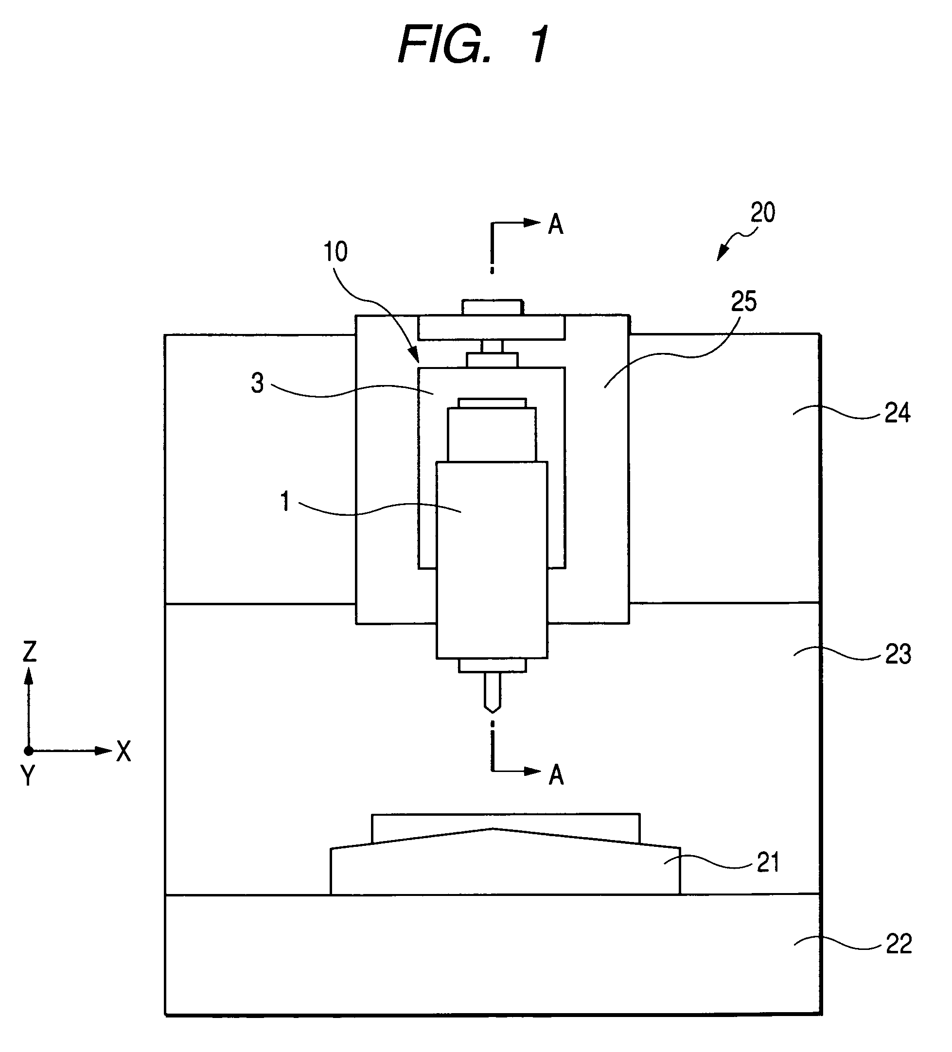
[0052]FIG. 3 is a sectional view showing a first embodiment and is taken along line A-A of FIG. 1. As shown in FIG. 3, the sliding portion of the pneumatic cylinder 3 for passing the cylinder rod 5 therethrough is provided with a ball guide bushing 8.

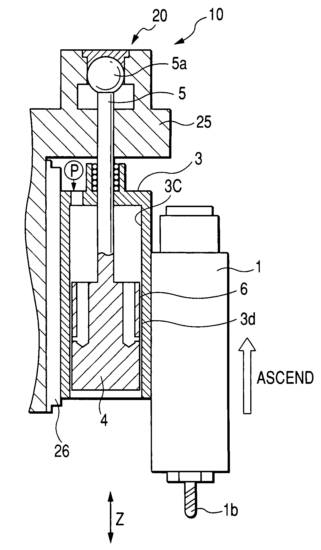
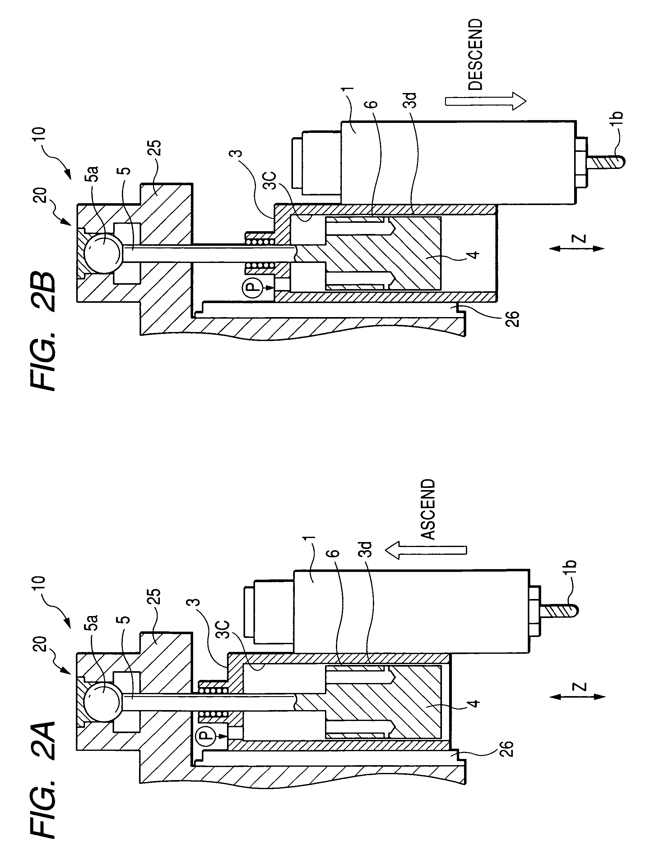
[0053]Once the compressed air flows from an air pressure source P such as a compression pump into the interior 3c of the pneumatic cylinder 3, the pneumatic cylinder 3 is ascended by a pressure P1 to counterbalance or lightening the gravitational load which is generated by the weight of the main spindle head 1 or the pneumatic cylinder 3.

[0054]The piston 4 is provided with a plurality of air communication holes 4a, each of which has its one end opened to communicate with the cylinder interior 3c of the pneumatic cylinder 3. In the piston 4, there is formed static pressure nozzles 4b, which communicate with the air communication holes 4a from the outer peripheral portion of the piston 4. Via the static pressure nozzles 4b, the compressed...

second embodiment

[0060]FIG. 4 is a sectional view showing a second embodiment and is taken along line A-A of FIG. 1. As shown in FIG. 4, this second embodiment is characterized in that the piston 4 shown in FIG. 3 further includes a ring groove 4d, which is positioned on the upper side of vicinity of the central portion thereof. This ring groove 4d is provided with such an air exhaust 4e for the pneumatically static bearing 6 as extends radially inward. In the piston 4, on the other hand, an air exhaust 4f to communicate with the air exhaust 4e is formed to extend axially upward from the lower end face of the piston 4. The air exhaust 4f is connected to a valve 9g (as located on the right side of the drawing). In other words, the air exhausts 4e and 4f constitute a air exhaust passage having a first hole on the ring groove and a second hole on a lower face of the piston. The second hole connects the air exhaust passage with the valve 9g. The ring groove 4d is formed at a substantially intermediate p...

third embodiment

[0062]FIGS. 5A and 5B show a third embodiment, FIG. 5A is a sectional view taken along line A-A of FIG. 1, and FIG. 5B is a sectional view taken along line B-B of FIG. 5A. As shown in FIG. 5B, vertically extending vertical grooves 4g are formed in the outer circumference of the piston 4. These vertical grooves 4g are formed in plurality (e.g., twelve) and arranged equidistantly in the circumferential direction of the piston 4. As shown in FIG. 5A, the vertical grooves 4g have their lower end portions formed into a not-go shape. Specifically, the vertical grooves 4g are not provided entirely of the axial direction of the piston 4 but are formed to extend from the upper end of the piston 4 but to stop short of the lower end. At the lower end portion of the piston 4, moreover, there is formed a cylindrical face 4h which does not have the vertical grooves 4g. In short, the lower ends of the vertical grooves 4g do not reach to the lower end of the piston 4. According to this constitution...


PUM

PropertyMeasurementUnit
sizeaaaaaaaaaa
particle diameteraaaaaaaaaa

Abstract

A pneumatically static balancer for a machine tool counterbalances or lightens a gravitational load generated by an own weight of a vertically moving driven member. The pneumatically static balancer includes a pneumatic cylinder supporting the driven member and allowed to move vertically, a pneumatically static bearing having a piston inserted into the pneumatic cylinder, the pneumatic static bearing being formed by feeding compressed air, which is in an interior of the pneumatic cylinder, into a small clearance formed between the pneumatic cylinder and the piston, a cylinder rod connected to an upper end of the piston and a saddle supporting a leading end portion of the cylinder rod.

Description

BACKGROUND OF THE INVENTION[0001]1. Field of the Invention[0002]The present invention relates to a pneumatically static balancer for a machine tool to be used with a driven member of a vertical shaft.[0003]2. Description of the Background Art[0004]In a vertically moving drive device such as a main spindle head in a vertical machine tool or a saddle of a horizontal machine tool, there is known a balancer which has such a balancer mechanism as is compatible to weight of a driven member so as to prevent the driven member from falling or to apply no load to a motor at a stopping time. This balancer is categorized as a counter balancer type, a liquid pressure cylinder type using oil or water pressure, an air pressure cylinder type or the like. In these kinds of balancers, for aiming at reducing the space, a hydraulic cylinder, which is arranged coaxially with the driven member, is known.[0005]FIG. 7 is a conceptional diagram showing a known balance mechanism of a vertical machining cente...

Claims


Application Information

Patent Timeline
Patent Type & Authority Patents(United States)
IPC IPC(8): B23Q11/00B23B47/26
CPCB23Q1/38F15B15/1447B23Q11/001Y10T409/309688
Inventor TANIZAKI, AKIRATAKASE, AKIRAMURAI, SHIRO
Owner KOMATSU NTC LTD
Why Eureka
Try Eureka