
Delivery systems for embolic filter devices

a filter device and delivery system technology, applied in the field of filtering devices and systems, can solve the problems of emboli not being fully vaporized and thus entering the bloodstream, affecting the patient's health, and releasing emboli into the circulatory system can be extremely dangerous and sometimes fatal, and achieve the effect of eliminating additional steps

Inactive Publication Date: 2008-09-16
ABBOTT CARDIOVASCULAR
View PDF760 Cites 49 Cited by
  • Summary
  • Abstract
  • Description
  • Claims
  • Application Information

AI Technical Summary

Benefits of technology

This system effectively captures embolic debris, reduces procedural complexity, and minimizes the risk of embolic events by allowing for easier placement and retrieval of the filter device, enhancing the safety of vascular interventions.

Problems solved by technology

However, there is one common problem which can become associated with all of these non-surgical procedures, namely, the potential release of embolic debris into the bloodstream that can occlude distal vasculature and cause significant health problems to the patient.
Additionally, while complete vaporization of plaque is the intended goal during a laser angioplasty procedure, quite often particles are not fully vaporized and thus enter the bloodstream.
When any of the above-described procedures are performed in the carotid or arteries, the release of emboli into the circulatory system can be extremely dangerous and sometimes fatal to the patient.
Debris that is carried by the bloodstream to distal vessels of the brain can cause these cerebral vessels to occlude, resulting in a stroke, and in some cases, death.
Therefore, although cerebral percutaneous translational angioplasty has been performed in the past, the number of procedures performed has been limited due to the justifiable fear of causing an embolic stroke should embolic debris enter the bloodstream and block vital downstream blood passages.
However, it is often difficult to control the size of the fragments which are formed, and the potential risk of vessel occlusion still exists, making such a procedure in the carotid arteries a high-risk proposition.
However, as mentioned above, there have been complications with such systems since the vacuum catheter may not always remove all of the embolic material from the bloodstream, and a powerful suction could cause problems to the patient's vasculature.
Other techniques which have had some limited success include the placement of a filter or trap downstream from the treatment site to capture embolic debris before it reaches the smaller blood vessels downstream.
However, there have been problems associated with filtering systems, particularly during the expansion and collapsing of the filter within the body vessel.
If the filtering device does not have a suitable mechanism for closing the filter, there is a possibility that trapped embolic debris can backflow through the inlet opening of the filter and enter the blood-stream as the filtering system is being collapsed and removed from the patient.
In such a case, the act of collapsing the filter device may actually squeeze trapped embolic material through the opening of the filter and into the bloodstream.
However, this procedure causes the physician to perform additional steps which are time-consuming due to the increased number of times that the physician has to maneuver the filtering device and additional guide wire into the patient's vasculature.

Method used


Image

  • Delivery systems for embolic filter devices
  • Delivery systems for embolic filter devices
  • Delivery systems for embolic filter devices

Examples


Embodiment Construction

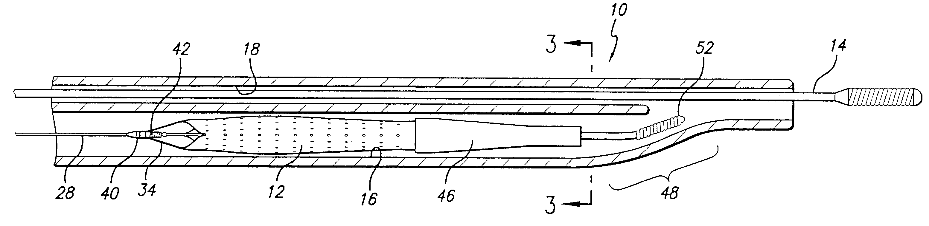
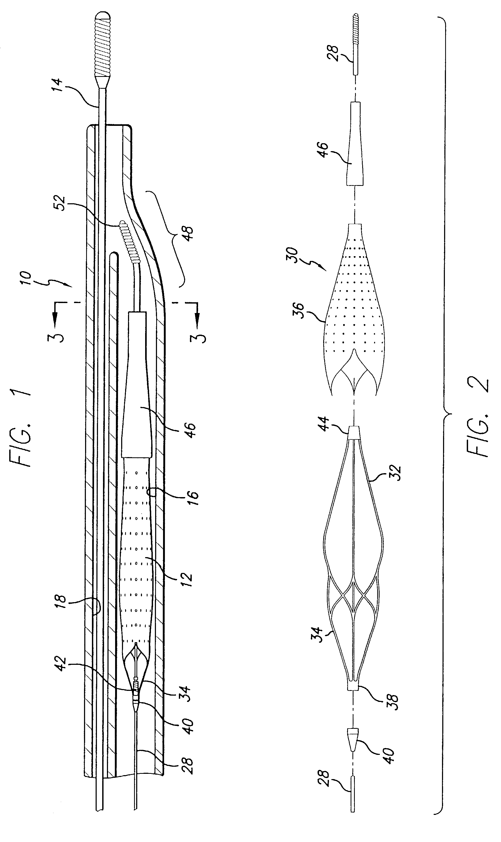
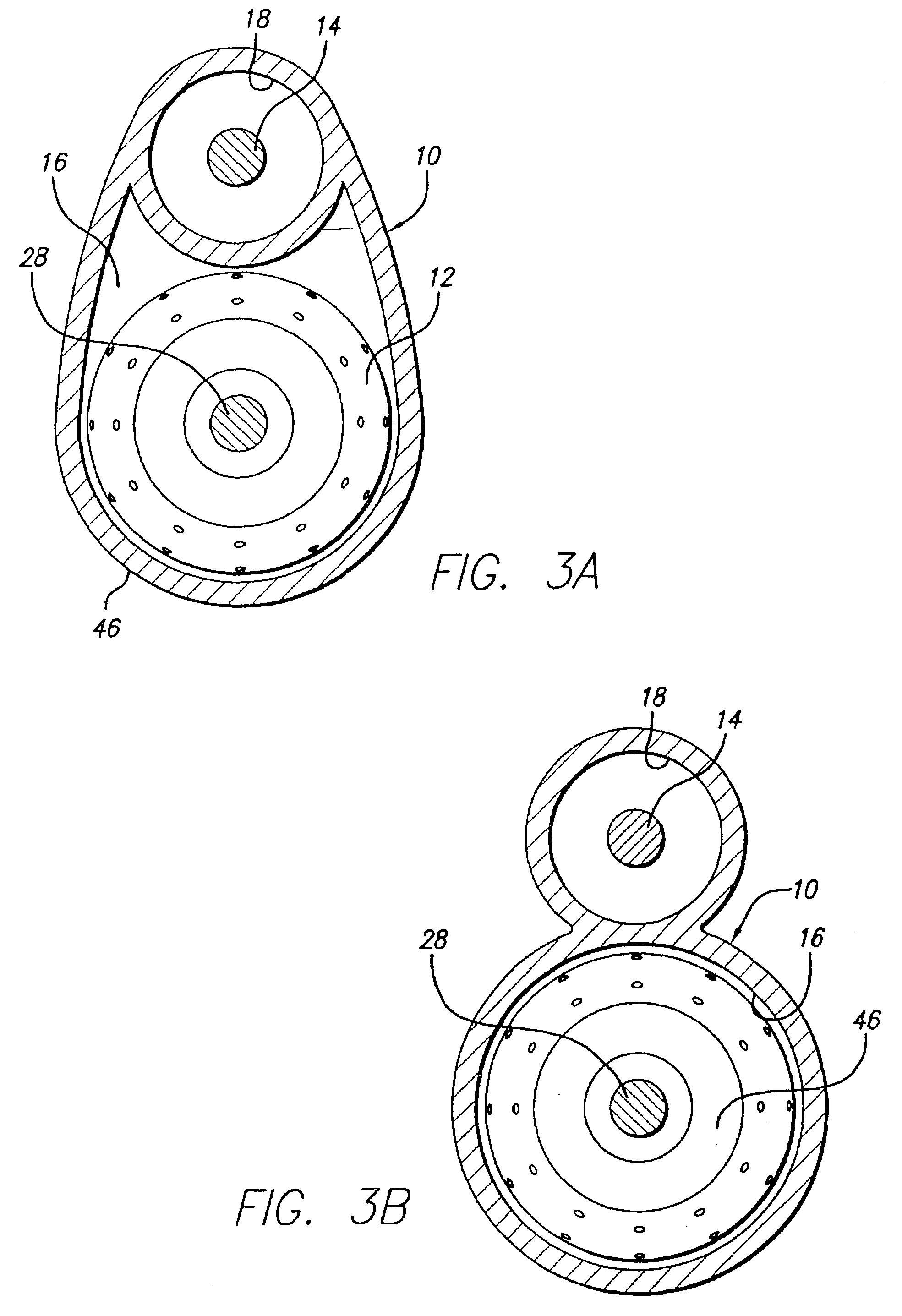
[0037]Turning now to the drawings, in which like reference numerals represent like and corresponding elements in the drawings, FIG. 1 represents a dual lumen delivery sheath 10 incorporating features of the present invention. In the particular embodiment shown in FIG. 1, the dual lumen delivery sheath 10 is adapted to receive both an expandable filter device 12 and a primary guide wire 14. The delivery sheath 10 includes a pair of lumens, namely, a filter lumen 16 which is adapted to receive the expandable filter device 12 and a guide wire lumen 18 which receives the primary guide wire 14. As is shown in FIGS. 4-6, the delivery sheath 10 can be placed within an artery 20 or other blood vessel of a patient. This portion of the artery 20 has an area of treatment 22 in which arthroscopic plaque 24 has built up against the inside wall 26 of the artery 20. In use, the filter device 12 is to be placed distal to, and downstream from, the area of treatment 22, as shown in FIG. 6. Methods fo...


PUM


Abstract

A delivery system for an expandable filter device includes a dual lumen delivery sheath which has a lumen for receiving the expandable filter device and a lumen for receiving a primary guide wire. The primary guide wire is utilized to place the delivery sheath and expandable filter into the desired region of the patient's vasculature via an over-the-wire or rapid-exchange arrangement. The delivery sheath can be protracted over the expandable filter device to allow the filter to be deployed within the patient's vasculature at the desired location. The delivery system can be embodied in an alternative design in which the primary guide wire extends through a guide wire lumen located in an obturator which forms part of the expandable filter device. Again, the primary guide wire is utilized to maneuver the filter device into the desired area via an over-the-wire arrangement. A slit extending longitudinally along the length of the sheath facilitates the removal of the guide wire and delivery sheath from the patient's vasculature.

Description

[0001]This application is a continuation of application Ser. No. 09 / 691,463 filed Oct. 17, 2000, now U.S. Pat. No. 6,537,294 which is assigned to the same Assignee as the present application.BACKGROUND OF THE INVENTION[0002]The present invention relates generally to filtering devices and systems which can be used when an interventional procedure is being performed in a sensed or occluded region of a blood vessel to capture embolic material that may be created and released into the bloodstream during the procedure. The system of the present invention is particularly useful when performing balloon angioplasty, stinting procedures, laser angioplasty, atherectomy, or other interventional procedures in critical vessels, particularly in vessels such as the carotid arteries, where the release of embolic debris into the bloodstream can occlude the flow of oxygenated blood to the brain or other vital organs, which can cause devastating consequences to the patient. While the embolic protectio...

Claims


Application Information

Patent Timeline
Patent Type & Authority Patents(United States)
IPC IPC(8): A61M29/00A61F2/01A61F2/06A61F2/84A61M25/06
CPCA61F2/013A61F2/95A61M25/0668A61F2230/008A61F2230/0006A61F2230/0067A61F2002/018
Inventor BOYLE, WILLIAM J.HUTER, BENJAMIN C.HUTER, SCOTT J.
Owner ABBOTT CARDIOVASCULAR
Learn More