Centrifugal fan clutch for an electronics cooling fan

a technology of electronics cooling fan and centrifugal fan, which is applied in the direction of wind motors, waterborne vessels, machines/engines, etc., can solve the problems of increasing the difficulty of system design within power and heat dissipation allowances, generating a significant amount of heat for electronic equipment contained within the enclosure, and affecting the cooling effect of electronic equipmen

Inactive Publication Date: 2008-09-16
HEWLETT-PACKARD ENTERPRISE DEV LP
View PDF14 Cites 12 Cited by
  • Summary
  • Abstract
  • Description
  • Claims
  • Application Information

AI Technical Summary

Problems solved by technology

Electronic equipment contained within the enclosure generates a significant amount of heat.
Thermal damage may occur to the electronic equipment unless the heat is removed.
In recent years electronic systems have become more densely packaged so that system design within power and heat dissipation allowances has become more difficult.
This system evolution creates design challenges in aspects of power consumption and the effect of fans on overall system heat dissipation characteristics.
If one or more of the series-connected fans fails due to any of various mechanical or electrical failures, power failure or shutdown due to attempts to operate above a system power budget, physical obstruction of a fan rotor, or the like, the failed fan may create a drag on cooling airflow through the system.
Drag in the airflow pathway can result in increased demand on other fans, overheating of electronic components and devices, and degradation in electronics performance.
Electronics cooling fans typically fail when motor bearing lubricant dries, which may result in a locked rotor.
Fan failure may create heavy resistance to airflow through the electronics system due to blockage created by stationary fan blades.

Method used


Image

  • Centrifugal fan clutch for an electronics cooling fan
  • Centrifugal fan clutch for an electronics cooling fan
  • Centrifugal fan clutch for an electronics cooling fan

Examples


Embodiment Construction

[0009]A common cause of failure in an electronics cooling fan is drying of motor bearing lubricant. Dried lubricant can result in a locked rotor, which may create a massive resistance to air flow through an electronics system due to blockage of stationary fan blades. Additional of a simple centrifugal clutch to a fan enables the fan blades to rotate freely, thereby reducing flow resistance.

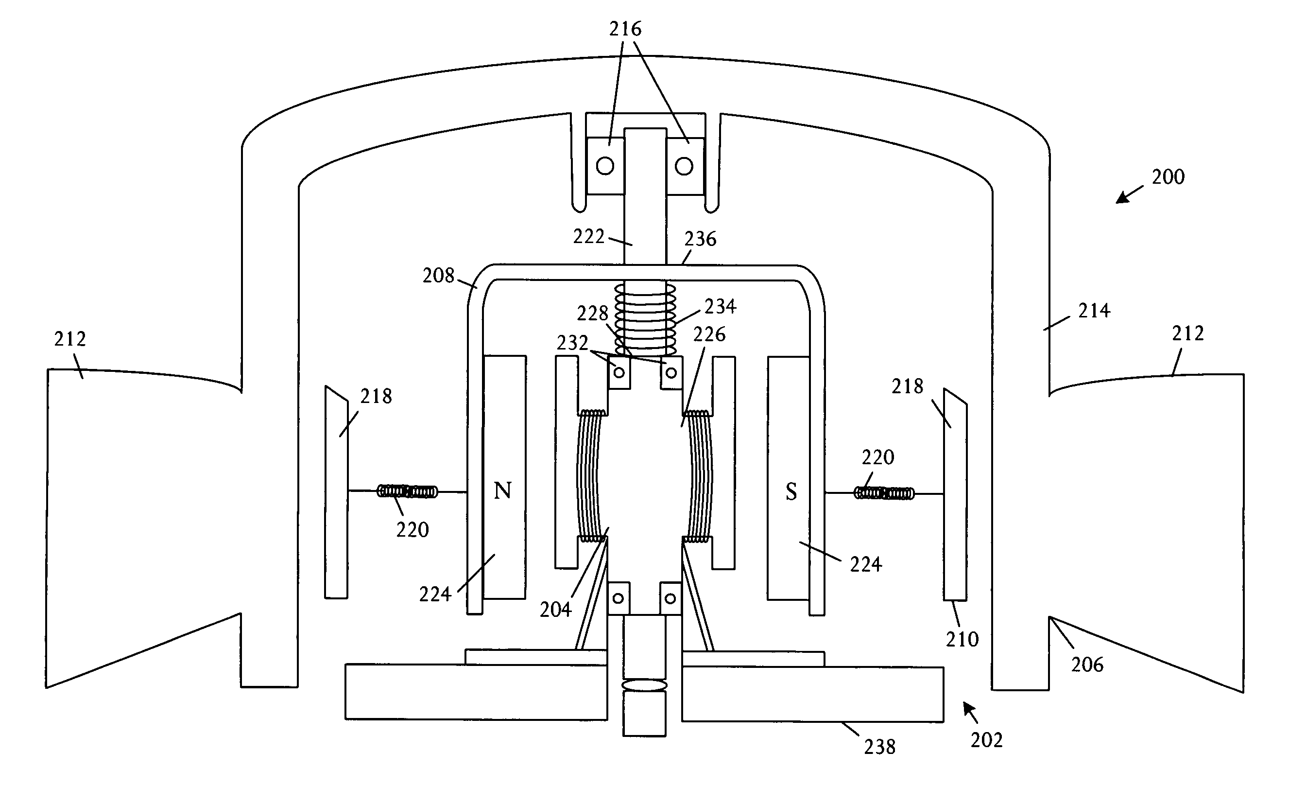
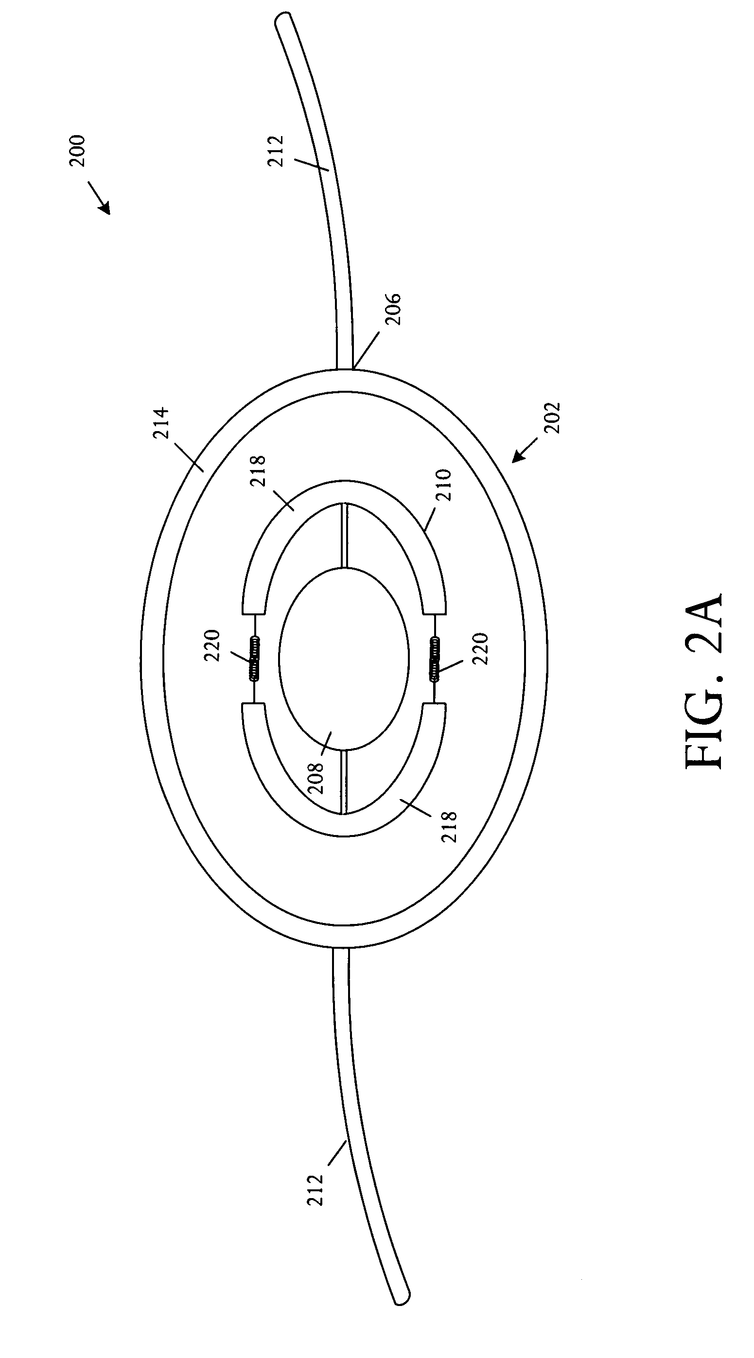
[0010]A centrifugal clutch is activated and deactivated on the basis of applied centrifugal forces in a simple, effective structure and technique that is triggered by rotation of an attached fan motor. When the motor slows or stops, the centrifugal clutch disengages, enabling the fan blades to rotate independently of the motor. The centrifugal clutch may be implemented in a fully mechanical structure.

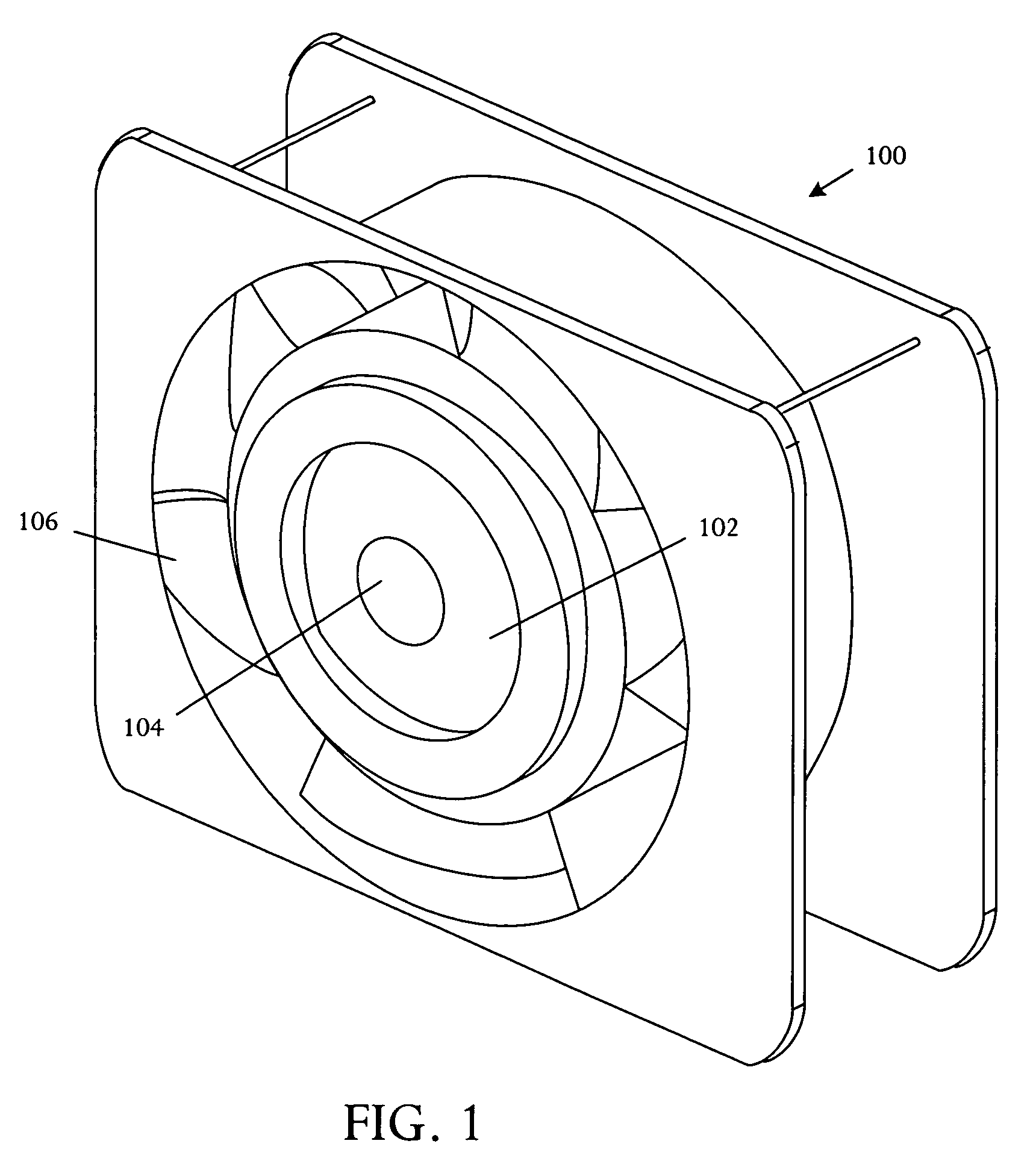
[0011]Referring to FIG. 1, a perspective pictorial diagram illustrates an embodiment of an electronics cooling fan 100 comprising a centrifugal clutch 102 which is adapted to disengage and freewheel u...


PUM


Abstract

An electronics cooling fan comprises a centrifugal clutch adapted to disengage and freewheel upon fan failure.

Description

BACKGROUND OF THE INVENTION[0001]Electronic systems and equipment such as computer systems, network interfaces, storage systems, and telecommunications equipment are commonly enclosed within a chassis, cabinet or housing for support, physical security, and efficient usage of space. Electronic equipment contained within the enclosure generates a significant amount of heat. Thermal damage may occur to the electronic equipment unless the heat is removed.[0002]Electronic systems commonly include heat-dissipating components such as processors, central processing units (CPUs), signal processors, and others. One or more fans are used to push air through the system and over components to avoid overheating of the heat-dissipating components. In recent years electronic systems have become more densely packaged so that system design within power and heat dissipation allowances has become more difficult. This system evolution creates design challenges in aspects of power consumption and the eff...

Claims


Application Information

Patent Timeline
Patent Type & Authority Patents(United States)
IPC IPC(8): H05K7/20F01D15/12F04B9/00H02K9/06
CPCF04D25/022G06F1/20F16D43/18F04D29/582
Inventor MALONE, CHRISTOPHER G.SIMON, GLENN C.ESPINOZA-IBARRA, RICARDO
Owner HEWLETT-PACKARD ENTERPRISE DEV LP
Why Eureka
Try Eureka