Pill crusher

a technology of crushers and pills, applied in the direction of pump control, positive displacement liquid engine, metal working apparatus, etc., can solve the problems of inhalation of airborne dust, difficulty in swallowing pills, and difficulty in swallowing pills, and achieve the effect of preventing cross-contamination

Active Publication Date: 2008-09-23
COUGAR MOUNTAIN MARKETING
View PDF14 Cites 21 Cited by
  • Summary
  • Abstract
  • Description
  • Claims
  • Application Information

AI Technical Summary

Benefits of technology

[0013]When the pill crusher according to the present invention is in operation, a paper cup is inserted into the receptacle, at least one pill is inserted into the paper cup and preferably, a second paper cup is inserted into the first paper cup, so that the pill or pills is / are located between the two paper cups in order to prevent cross-contamination. The electric motor is then energized under the control of the drive control so as to displace the plunger into the second paper cup and the recess in the receptacle until reaching a first predetermined distance or a predetermined pressure, which is sufficient to ensure that the pill is broken into segments or crushed. During this stroke, the plunger is rotated by the worm and nut drive, so that the pill is subjected to both rotational forces and compression forces, and the pill is broken into segments or crushed, the plunger terminating its downward movement at a distance from the bottom of the recess or at the predetermined pressure. The plunger is subsequently displaced from the pill, under the control of the drive control, and may be again displaced toward the pill through a second predetermined stroke to break the pill or pills into smaller segments. During this second predetermined stroke, the plunger is again rotated by the worm and nut drive transmission. The plunger is subsequently again displaced from the pill segments, under the control of the drive control, and may be again displaced toward the pill through a third predetermined stroke to ensure that each pill is pulverized by crushing and grinding into a fine powder. During this third stroke, the plunger is again rotated by the worm and drive transmission.

Problems solved by technology

Some patients for whom medication is provided in the form of pills, because of their poor medical conditions, have difficulty in swallowing the pills.
At the present time, pills are usually crushed by employing a manual pill crusher, but this frequently results in the manual exertion of high forces, or postures and repetitive movements that can contribute to injuries of the hands, wrists and shoulders.
Furthermore, inhalation of airborne dust, which occurs during the crushing process, has also been reported to be a problem.
However, even with the use of such lever-type mechanical devices, the forces required are often still high, and the users are still required to assume awkward postures and to perform repetitive movements.
Awkward postures of the shoulder occur because pill crushers are typically placed on the tops of medication carts and the heights of the top surfaces of the medication carts are usually too high for most workers.
The design of a typical lever-type crusher is such that downward forces are required to be exerted on a straight handle, which results in awkward postures of the wrist.
However, this prior device has the disadvantage that it is necessary to press the plunger down manually toward the turntable, which is resiliently mounted, so that the crushing forces which can be exerted on the pill are limited.
Another disadvantage of this prior device is the risk that rotation of the turntable could be initiated by pressing directly onto the turntable with, for example, a finger, while the plunger is removed.
However, this prior device has the disadvantage that it employs rotary blades, which can pose a safety hazard.
However, this prior device has the disadvantage that the ram does not rotate while being displaced, so that the crushing abilities which can be exerted on the pill are limited.
Another disadvantage of this prior device is the use of a compression spring to retract the plunger, which may weaken its ability to retract the plunger over time.

Method used


Image

  • Pill crusher
  • Pill crusher
  • Pill crusher

Examples


first embodiment

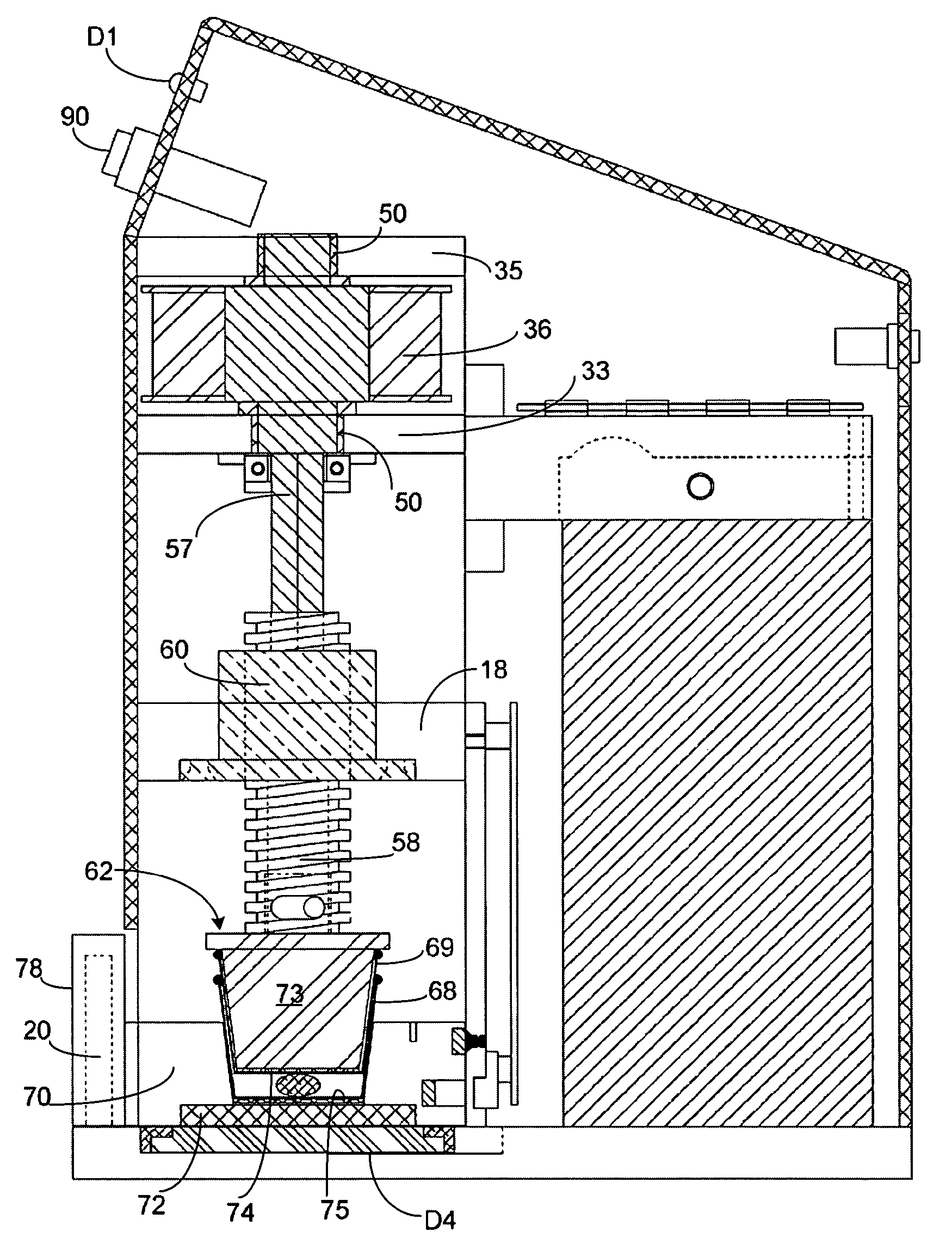
[0043]In FIG. 2A of the first embodiment platform 18 projects forwardly from the side walls 16 and is supported on a pair of posts 20 and 21 at opposite front corners of the pill crusher. At the rear of the pill crusher, there is provided a low noise electric motor 22 (as seen in FIG. 3A) having a vertical axis.

second embodiment

[0044]In FIG. 2B of the second embodiment there is provided a low noise electric motor 22 (as seen in FIG. 3B) having a vertical axis, at the front of the pill crusher.

[0045]As shown in FIGS. 3A and 3A(i) of the first embodiment, the electric motor 22 has a drive shaft 24, which carries a gear 26 meshing with a gear 28 mounted on a vertical shaft 30, which is journaled at its lower end in a base plate 32 and, at its upper end, in a platform 34 on which the motor 22 is mounted. A further gear 36 on the shaft 30 meshes with a gear 38 on a shaft 40, which is also journaled at opposite ends in the base plate 32 and platform 52. A gear 42 on the shaft 40 meshes, in turn, with a gear 44 mounted on the lower end of a vertical shaft 46. The shaft 46 is journaled at opposite ends in bearings 48 and 50. The bearings 48 are mounted in the platform 34 and 52 at the lower end of the shaft 46, and the bearings 50 are mounted in a pair of vertically spaced platforms 54, which extend between the si...


PUM


Abstract

A pill crusher has a paper cup receptacle having an upwardly open, frusto-conical recess for receiving a paper cup, a plunger having a frusto-conical shape complimentary to that of the recess, the plunger being above and coaxial with the recess, an electric motor and a reciprocating drive transmission between the electric motor and the plunger for displacing the plunger into and out of the recess. The reciprocatory drive transmission comprises a worm and nut drive transmission for rotating the plunger while displacing the plunger into the receptacle. A drive control connected to the electric motor controls the motor so as to displace the plunger into and out of the recess.

Description

FIELD OF THE INVENTION[0001]The present invention relates to pill crushers and, more particularly, to electrically operated pill crushers.[0002]The present application claims priority from Canadian Patent Application Serial Number 2,447,753, filed Nov. 3, 2003, entitled “Pill Crushers”.BACKGROUND OF THE INVENTION[0003]Some patients for whom medication is provided in the form of pills, because of their poor medical conditions, have difficulty in swallowing the pills. It has therefore previously been proposed to provide a pill crusher, by means of which pills can be crushed into a powder form. The powder produced in this way can then be added to a liquid to provide a mixture which is more easily consumable by such patients.[0004]In most healthcare facilities, crushing pills for patients is a frequently performed task. At the present time, pills are usually crushed by employing a manual pill crusher, but this frequently results in the manual exertion of high forces, or postures and rep...

Claims


Application Information

Patent Timeline
Patent Type & Authority Patents(United States)
IPC IPC(8): A47J42/00A61J7/00B02C19/08
CPCB02C19/08A61J7/0007
Inventor HALL, RICKROBINCE, DANENGST, CHRISBACK, CHRISKEENE, BRIANGRAIG, MATTJANZEN, EMIE
Owner COUGAR MOUNTAIN MARKETING
Why Eureka
Try Eureka