Method and apparatus for scanning optical delay line

a delay line and optical delay technology, applied in the field of optical interferometry systems, can solve the problems of attenuated recombined beam, system limitation to repetition rate, 100 hz, etc., and achieve the effect of good performan

Active Publication Date: 2008-09-23
NAT RES COUNCIL OF CANADA
View PDF12 Cites 13 Cited by
  • Summary
  • Abstract
  • Description
  • Claims
  • Application Information

AI Technical Summary

Benefits of technology

[0013]Higher stability and higher repetition rates can be obtained from the use of uniformly rotating elements since high-speed rotating motors with high rotation stability are commercially available. Examples of such designs are the use of the reflection from the side of a multi-segment CAM (as taught in U.S. Pat. No. 6,191,862 to Swanson et al.) or from the surface of a helicoidal mirror (U.S. Pat. No. 5,907,423 to Wang et al.). These can attain high repetition rates in the kHz range, good linearity, and high duty cycles. Unfortunately such designs require careful machining and alignment.
[0030]One advantage of using a prism as the parallelogram optical path element is improved linearity, and one advantage of using parallel mirror configuration of the parallelogram optical path element is a reduction in dispersion. Dispersion can also be minimized by appropriate selection of the material of which the prism is fabricated.

Problems solved by technology

If the parts of the beams are out of phase with respect to each other, they will destructively interfere, resulting in an attenuated recombined beam.
If the parts of the beams are in phase, they will constructively interfere, and the recombined beam will maintain (substantially) the power of the incident light beam.
For scanning ranges of the order of a few millimeters like those usually required in OCT, such systems are limited to repetition rates of the order of 100 Hz, which is too low for real-time imaging.
Additionally, such systems also require acceleration and deceleration of a given mass impacting robustness and linearity.
Higher repetition rates can be obtained with a galvanometer in a resonance mode, but at the cost of a higher nonlinearity and lower duty cycle.
Unfortunately such designs require careful machining and alignment.
High repetition rates are achievable, however the system taught by Fercher suffers from non-linearity and a low duty cycle.
These designs suffer from one or more of the following: low-duty cycle, nonlinearity, difficult alignment, and lack of robustness.
Such a design can achieve high scanning rates but suffers from high power requirements, poor mechanical and temperature stability, and induced birefringence effects.
The design involves a “double-pass” optical arrangement usable in retroreflective configuration, which makes the already complex setup even more so.
The optical alignment is delicate because many parameters must be considered simultaneously: beat frequency, distance from a focal point of lenses, dispersion compensation, and optical delay.
Mechanical stability may be exceedingly difficult for use in an industrial environment or for achieving high accuracy.
The optical path length is fairly long (requiring a considerable coherence length of the incident light beam) and the number of optical components makes the design difficult to miniaturize.
Furthermore an amplitude of the output signal varies as the mirror moves away from the focal point, posing another constraint on the design.

Method used


Image

  • Method and apparatus for scanning optical delay line
  • Method and apparatus for scanning optical delay line
  • Method and apparatus for scanning optical delay line

Examples


first embodiment

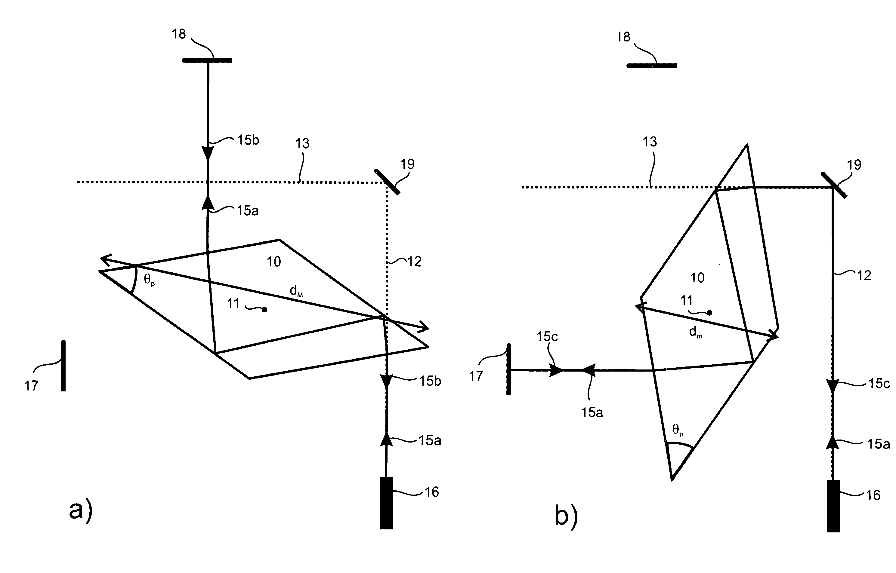
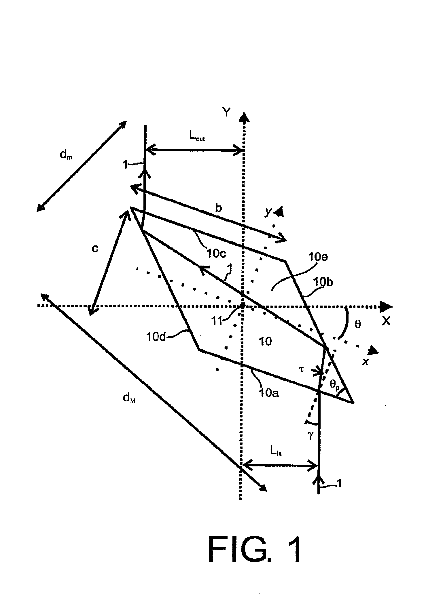
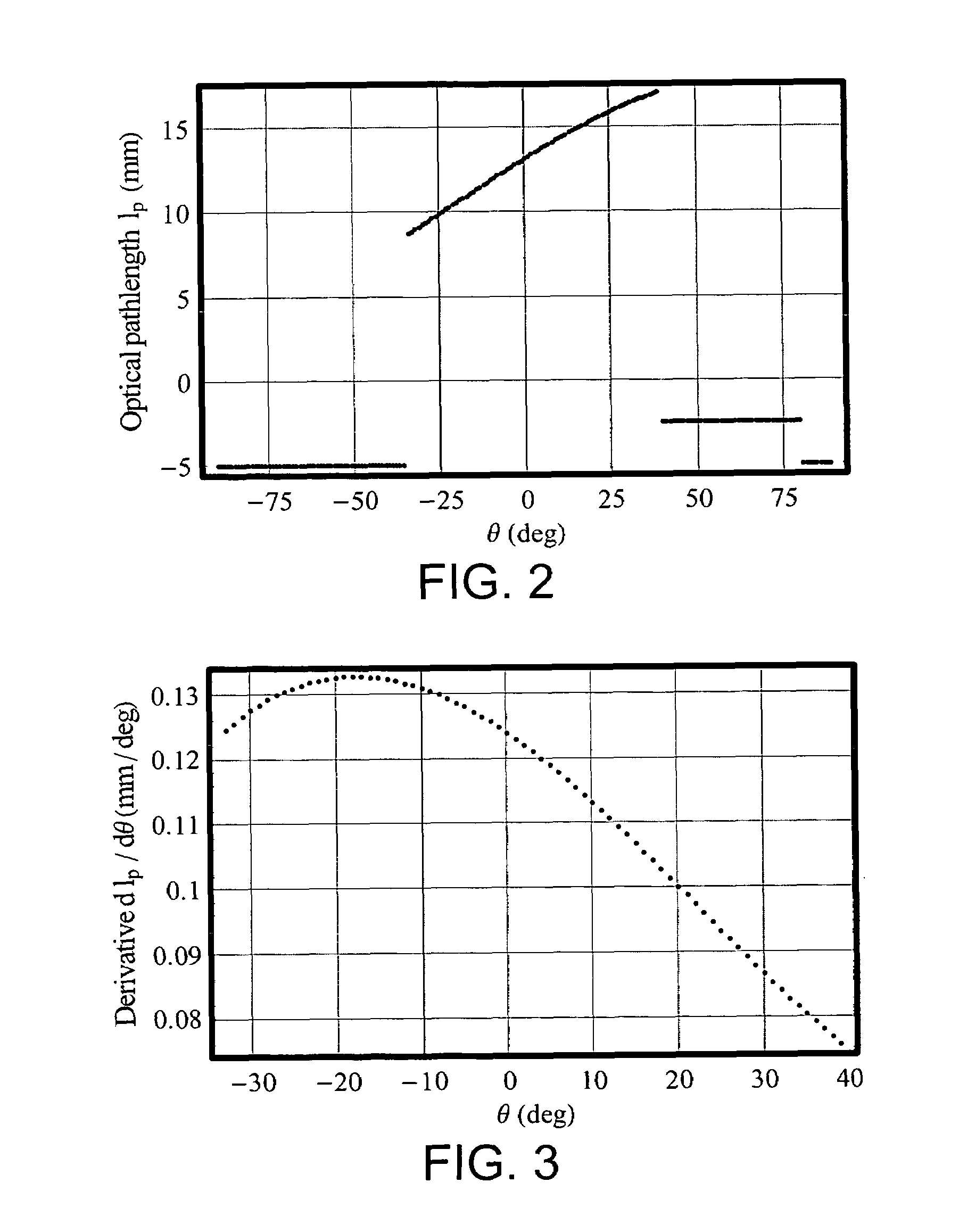
[0070]FIGS. 7a,b schematically illustrate the invention showing how multiple insertions of the beam may be achieved. A prism 10, is mounted for rotation about an axis 11 passing through its centroid, orthogonally to parallelogram top and bottom bases of the prism 10, as in FIG. 1. The scanning optical delay line assembly also includes two mirrors 17, 18 each for reflecting (by 180°) beams passing through the prism 10 at two ranges of angular positions, and a third mirror 19 for reflecting the beam from a line of incidence 12 with the prism 10 over a first range of angles, and a reinsertion line 13 that intersects the prism 10 over a second range of angular positions.

[0071]In FIG. 7a, a beam 15a exits an optical coupler 16 along a line of Incidence 12. Incidence line 12 is directed orthogonally to the rotational axis 11 from which it is offset by the distance Lin, as defined in FIG. 1. The distance Lin is Intermediate one half a major diagonal (dM) of the prism 10 and one half a mino...

second embodiment

[0074]the invention uses off centroid rotation which improves the selection of the range of angles the line of incidence makes with a front face of the prism. By rotating off centroid, only one surface is used as the front surface, and consequently there is no alternation of front and rear surfaces to double the number of times the beam is inserted in the prism, per cycle. Accordingly multiple prisms may be used to improve the duty cycle.

[0075]An example of the second embodiment is schematically illustrated in FIGS. 8a,b. The scanning optical delay line includes five prisms 31-35 fixed on a rotating disc 25. Each of the prisms 31-35 is oriented in a rotationally symmetric manner so that they all provide substantially the same range of angular variances with respect to lines of incidence 27 and reinsertion 28. Basically this embodiment has two additional parameters for optimization: a radial distance R of a centroid of the prism from the rotational axis; an angle θ0 between a radial ...


PUM


Abstract

A scanning optical delay line includes an optical path element that rotates about its central axis, such that a face is intermittently incident a beam of light to be optically delayed. When the beam is not incident the face, it is reflected onto a reinsertion line which provides a second opportunity for the beam to intersect the optical path element. The optical path element may include one or more parallelogram prisms, or parallel reflective surfaces to provide a substantially linear optical path length variation during the scan, which is produced by the rotation of the optical path element. A highly linear part of the rotation can be maximally used providing a high duty cycle, high linearity scanning optical delay line that permits high quality, high data rate applications.

Description

[0001]This application is a continuation-in-part of U.S. Ser. No. 11 / 254,748 filed Oct. 21, 2005 now abandoned.[0002]The present invention relates in general to optical interferometric systems, and in particular to scanning optical delay lines of an interferometric system.[0003]Interferometric systems are deployed in a wide and growing number of applications. Typically, interferometric systems involve two arms, a beam splitter and a beam combiner. A beam of light incident the beam splitter is divided in two: one part of the beam is directed down each of the arms. The two parts are then recombined at a beam combiner. If the parts of the beams are out of phase with respect to each other, they will destructively interfere, resulting in an attenuated recombined beam. If the parts of the beams are in phase, they will constructively interfere, and the recombined beam will maintain (substantially) the power of the incident light beam. If the incident light beam emanates from a broadband so...

Claims


Application Information

Patent Timeline
Patent Type & Authority Patents(United States)
IPC IPC(8): G02B26/08
CPCG02B26/06G02B17/023G02B26/0816
Inventor DUFOUR, MARC L.LAMOUCHE, GUYGAUTHIER, BRUNO
Owner NAT RES COUNCIL OF CANADA
Why Eureka
Try Eureka