Eureka AIR delivers breakthrough ideas for toughest innovation challenges, trusted by R&D personnel around the world.

Modular welding system

a welding system and module technology, applied in the direction of welding devices, soldering devices, manufacturing tools, etc., can solve the problems of increasing the difficulty of controlling the molten weld puddle, the correspondingly more expensive and time-consuming weld, and the associated difficulty of making vertical welds, so as to reduce the extensive set up time or the use of heavy equipment. , the effect of quick and easy fabrication

Inactive Publication Date: 2008-09-30
ESKANDARI AMIR
View PDF10 Cites 25 Cited by
  • Summary
  • Abstract
  • Description
  • Claims
  • Application Information

AI Technical Summary

Benefits of technology

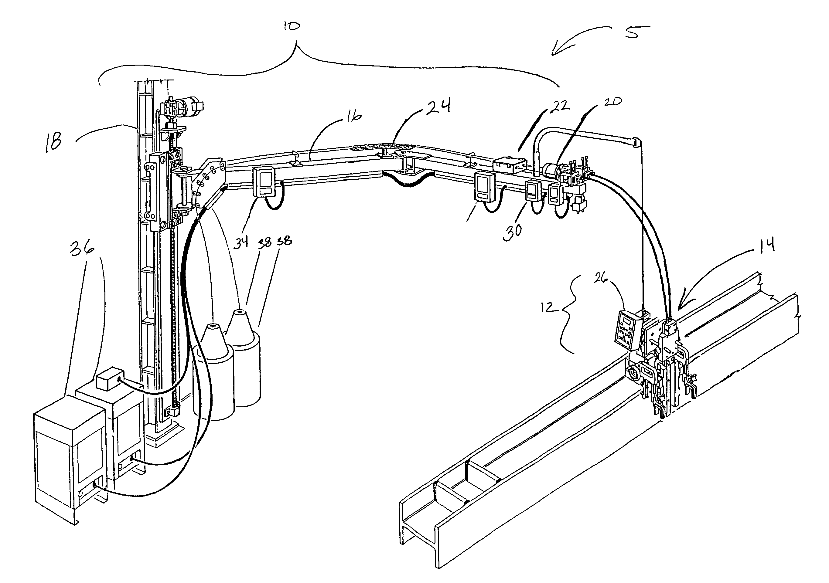
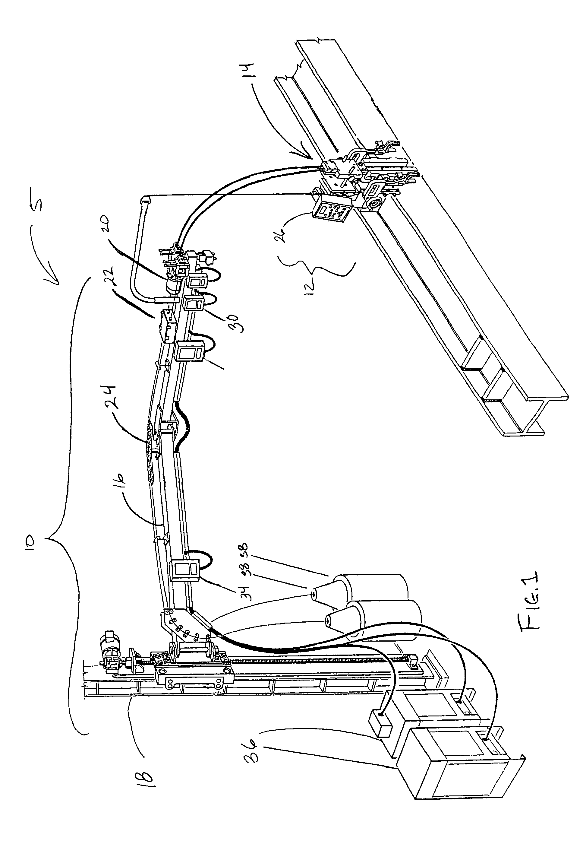
[0017]The present invention is a modular welding system which allows quick and easy fabrication of high quality vertical welds under varying conditions, reducing extensive set up time or use of heavy equipment. The modular welding system is comprised of two main groups, a basic component system and a modular fixture component system. Preferably, all of the components associated with the basic component system are coupled to an articulated boom. Each of the modular fixture systems is suspended from the end of the articulated. Each modular fixture component system has a particular fixture assembly that performs a particular type of weld, yet can still interface with the same basic component system.

Problems solved by technology

With vertical welding of metal substrates, the molten weld puddle is much more difficult to control, and the weld is correspondingly more expensive and time-consuming to perform.
The problems associated with making vertical welds are particularly evident in the welding of “stiffener” plates into steel I beams or H columns for use in building construction.
The welding of stiffeners into structural beams is one of the most common welding operations and consumes thousands of man-hours per year for a typical structural steel fabricator.
If the gap is too wide, the weld will require more metal (and thus more weld passes) to fill.
Such removal is difficult and expensive, and generally requires gouging out the backup bars with a carbon arc, followed by additional weld passes to fill in the gouged areas.
This process is very time consuming and expensive.
Again the removal of this backup bar is very time consuming and expensive.
Handling and positioning the vertically oriented columns is difficult and requires an overhead crane and the use of a pit and / or platform, thus requiring a large amount of work space.
Further, the location of the welding operation is generally not at ground or floor level when using pit or platform welding techniques, and can require the welding operator to be awkwardly or precariously positioned on a platform or ladder during the welding operation.
While the electroslag process permits vertical welds, it has previously not met with much success due to the large amount of time required to set up prior to welding.
Particularly, it is difficult and time consuming to position and secure the copper shoes about the gap between the substrates that are to be welded.
Another drawback associated with conventional electroslag welding is that that the guide tube must be carefully positioned within the gap to be welded, which requires careful alignment of the welding head and welding oscillator mechanism.
Incorrect alignment of the guide tube can result in contact of the guide tube with tone of the copper shoes during welding, causing a 500 to 2000 Amp short, which will generally destroy the (expensive) copper welding shoe and interrupt the welding operation.
Any such interruption of an electroslag weld operation is very inconvenient, and expensive, and generally requires gouging out the incomplete weld and starting the entire operation over.
Still another drawback of conventional electroslag welding is that the molten flux puddle in the weld cavity can cause the welding wire to fuse to the bottom of the guide tube during welding, which prevents wire from feeding into the weld.
As noted above, the interruption of an electroslag weld in such a manner requires expensive and time consuming cleanup of the incomplete weld followed by starting the weld operation over again.
Welding controllers or control systems have been developed to facilitate electroslag welding by controlling wire feed rate, welding power supply output, and oscillation, but such controllers generally bulky and heavy, and typically provide for only one type of weld condition.
If the weld condition varies during welding, defects may occur to the weld, or a catastrophic short against one of the copper welding shoes may occur.
For these reasons, electroslag welding of stiffeners onto columns has not proved economical, and the welding industry has continued to use the flux-cored wire welding method.
These control systems are generally not scaleable or adaptable to changing needs or different types of welding operations.

Method used


Image

  • Modular welding system
  • Modular welding system
  • Modular welding system

Examples


Embodiment Construction

[0065]Referring more specifically to the drawings, for illustrative purposes the present invention is embodied in the system shown generally in FIG. 1 through FIG. 21. It will be appreciated that the system may vary as to configuration and as to details of the parts. The invention is disclosed generally in terms of heavy plate welding which may be applied to electroslag or electrogas welding. However, the invention may be used in a large variety of welding applications which employ a basic component system and a modular fixture component system, as will be readily apparent to those skilled in the art.

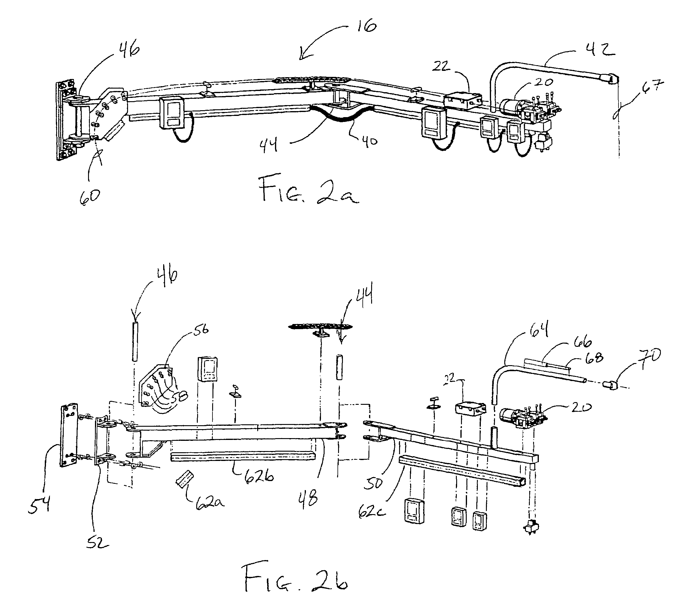
[0066]FIG. 1 is a perspective view of a welding system having a stiffener welding fixture. The welding system 5 includes a basic component system 10 and a modular fixture component system 12 which is a stiffener welding fixture 14. The basic component system 10 includes an articulated boom assembly 16, an articulated boom lift 18, a wire feeder 20, a motorized wire straightener 22, an a...


PUM

PropertyMeasurementUnit
thicknessaaaaaaaaaa
thickaaaaaaaaaa
thickaaaaaaaaaa

Abstract

A modular welding system for performing quick, easy and high quality welds. The modular welding system comprises a basic component system and a modular fixture component system. The basic component system provides the basic components which are needed to perform a quality weld efficiently. The modular fixture component system interfaces with the basic component system and provides a particular welding fixture assembly that performs a particular type of weld. More particularly, a stiffener type modular fixture component system and a butt / tee type modular fixture system are described. However, any other particular fixture type system may be integrated with the basic component system of the present invention.

Description

CROSS REFERENCE[0001]This patent application is a continuation application of patent application Ser. No. 09 / 804,686, (now abandoned) having a filing date of Mar. 12, 2001, which is a continuation-in-part of patent application Ser. No. 09 / 058,741 having a filing date of Apr. 10, 1998 and issuing as U.S. Pat. No. 6,297,472 on Oct. 2, 2001. This patent application is also related to provisional patent application 60 / 188,782 filed Mar. 13, 2000, which is hereby incorporated by reference.BACKGROUND OF THE INVENTION[0002]1. Field of the Invention[0003]This invention pertains generally to devices and methods for metal welding. More particularly, the invention is a modular welding system and method which provides for quick, easy and accurate vertical welds using a light weight, portable welding fixture.[0004]2. Description of the Background Art[0005]When welding metal items together using arc or gas welding techniques, horizontal welding has traditionally been easier and less expensive to ...

Claims


Application Information

Patent Timeline
Patent Type & Authority Patents(United States)
IPC IPC(8): B23K9/12B23K9/02B23K37/02
CPCB23K9/0203B23K9/0213B23K37/0235B23K9/122B23K2201/28B23K2101/28
Inventor BONG, WILLIAM L.BOCK, CHARLES A.
Owner ESKANDARI AMIR
Why Eureka
Eureka Blog
Learn More