Inverter device
a technology of inverter and capacitor, which is applied in the direction of emergency power supply arrangement, process and machine control, instruments, etc., can solve the problems of inability to accurately estimate the life of an electrolytic capacitor based on the measurement of the time constant, and the inability to change the electrostatic capacitance so as to facilitate the timing of replacement of the electrolytic capacitor
- Summary
- Abstract
- Description
- Claims
- Application Information
AI Technical Summary
Benefits of technology
Problems solved by technology
Method used
Image
Examples
embodiment 1
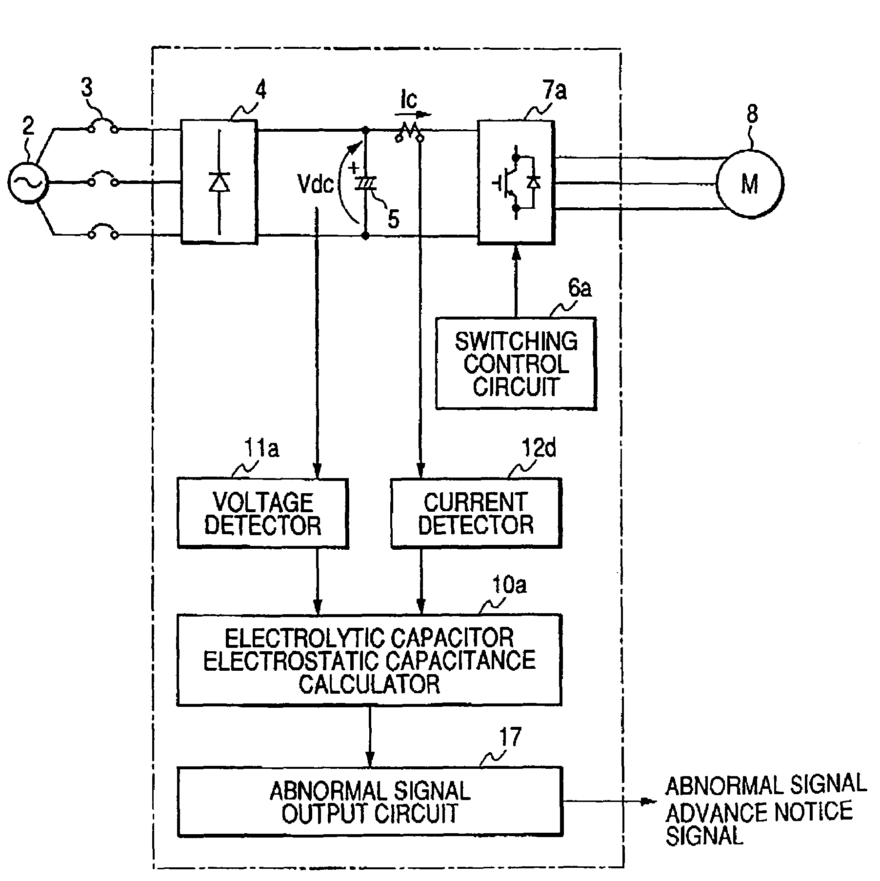
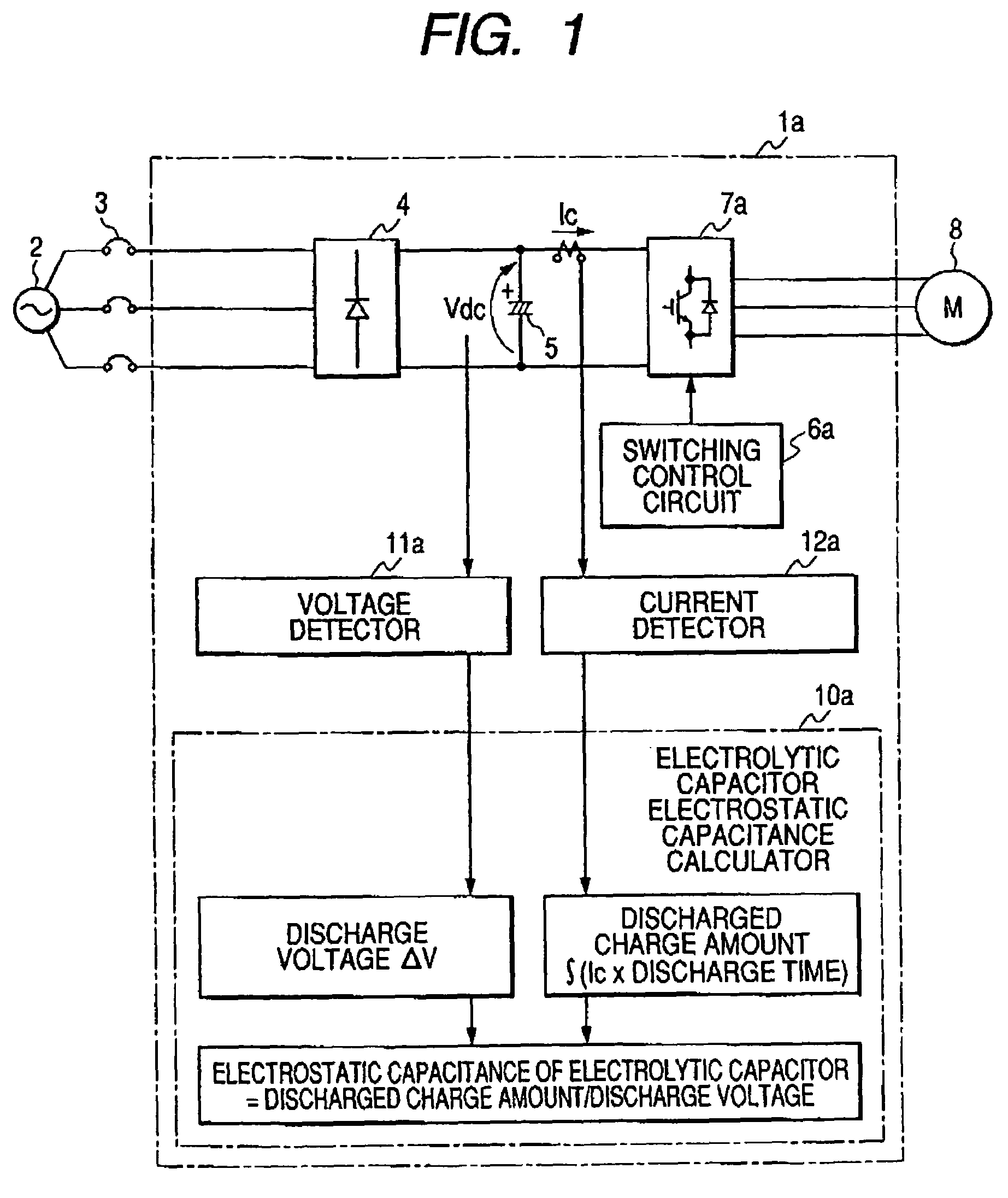
[0029]The configuration and process of an inverter device of Embodiment 1 of the invention will be described with reference to FIG. 1. Referring to FIG. 1, the inverter device 1a is connected to a commercial power source 2 through a breaker 3, a converter 4 converts the power-frequency AC voltage of the commercial power source 2 to a DC voltage, and the converted DC voltage is smoothed by an electrolytic capacitor 5. Switching elements constituting an inverter main circuit 7a are ON / OFF-controlled by a control signal from a switching control circuit 6a, whereby a DC power is converted to an AC power of predetermined frequency and voltage to drive an electric motor 8 serving as a load.
[0030]An electrolytic capacitor electrostatic capacitance calculator 10a comprises a timer which measures a discharge time in discharging of the electrolytic capacitor, and calculates the electrostatic capacitance of the electrolytic capacitor 5 on the basis of the voltage of the electrolytic capacitor ...
embodiment 2
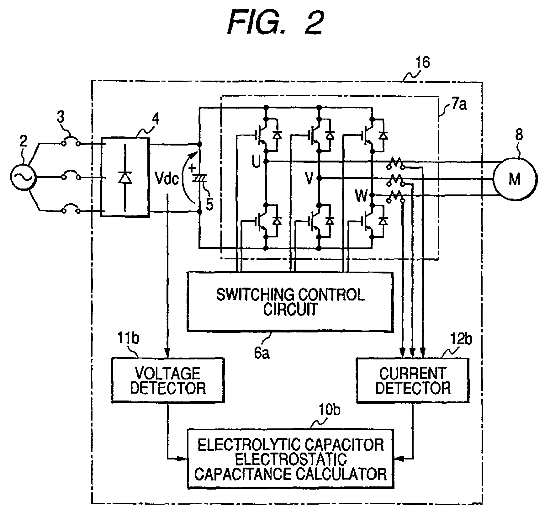
[0039]The configuration and process of an inverter device of Embodiment 2 of the invention will be described with reference to FIG. 2. In FIG. 2, 2 to 5, 6a, 7a, and 8 denote the same components as those of FIG. 1, and their description is omitted. A voltage detector 11b is configured so as to detect the voltage of the electrolytic capacitor 5, and obtain the discharge voltage ΔV which is a voltage drop from beginning of discharging. A current detector 12b is disposed for each phase of the output of the inverter main circuit 7.
[0040]An electrolytic capacitor electrostatic capacitance calculator 10b obtains a discharged charge amount of the electrolytic capacitor 5, from inverter output currents Iu, Iv, Iw of the phases detected by the current detector 12b, and a control signal which is output from the switching control circuit 6a, and which is used for ON / OFF-controlling the switching elements constituting the inverter main circuit 7, and calculates the electrostatic capacitance of ...
embodiment 3
[0048]The configuration and process of an inverter device of Embodiment 3 of the invention will be described with reference to FIG. 3. In FIGS. 3, 5, 8, and 11a denote the same components as those of FIG. 1, and their description is omitted. When the commercial power source is interrupted, a switching control circuit 6c outputs a control signal for ON / OFF-controlling only switching elements of the U phase, and for, with respect to the V and W phases, always turning OFF upper switching elements, and always turning ON lower switching elements. A current detector 12c is disposed on the output side of the U phase (the specific one phase which is to be ON / OFF-operated when the commercial power source is interrupted).
[0049]In an inverter main circuit 7c, diode elements 13 are connected in parallel to the lower switching elements of the two phases which are always turned ON, so that a circuit configuration is formed which ensures a current path in the state where, in the specific phase whi...
PUM
 Abstract
Description
Claims
Application Information
 - R&D
- Intellectual Property
- Life Sciences
- Materials
- Tech Scout
- Unparalleled Data Quality
- Higher Quality Content
- 60% Fewer Hallucinations
Browse by: Latest US Patents, China's latest patents, Technical Efficacy Thesaurus, Application Domain, Technology Topic, Popular Technical Reports.
© 2025 PatSnap. All rights reserved.Legal|Privacy policy|Modern Slavery Act Transparency Statement|Sitemap|About US| Contact US: help@patsnap.com


