Methods and apparatus for equalization in single-ended chip-to-chip communication

a single-ended chip and chip technology, applied in the field of communication, can solve the problems of voltage level loss of the edge that the driver drives onto the board trace, the loss of high-speed single-ended signaling over relatively long board traces, and the loss of voltage level of the higher frequency components of a voltage step, so as to improve the diminished voltage margin

Active Publication Date: 2008-10-07
ORACLE INT CORP
View PDF4 Cites 2 Cited by
  • Summary
  • Abstract
  • Description
  • Claims
  • Application Information

AI Technical Summary

Benefits of technology

[0010]In another embodiment, the adjustment of the reference voltage may improve a diminished voltage margin present during transmission of lonely 0's.
[0011]In a different embodiment, the adjustment of the reference voltage may improve a diminished voltage margin present during transmission of lonely 1's.

Problems solved by technology

High-speed single-ended signaling over relatively long board traces suffers from a number of important problems.
The first problem is inter-symbol interference (ISI), where because of the high-speed nature of the signaling, the driver switches before the previous bit completely attains its direct current (DC) level, thereby attaining voltage levels on succeeding bits as a function of the previous bits.
The second problem is low-pass characteristics of board traces that connect chips together, where the higher frequency components of a voltage step suffer greater losses than lower frequency components.
Third, the DC resistance of the long board trace also causes a voltage level loss of the edge that the driver drives onto the board trace.
Driver-side equalization, however, suffers from increased driver-caused switching noise on the driver power supply, thereby diminishing the performance achieved by this scheme.
Traditional receiver-side equalization techniques, such as minimum-mean-square equalization or decision-feedback equalization schemes, require the use of analog filters and therefore are difficult to implement in a complementary metal oxide semiconductor (CMOS) device.
Smaller voltage margins (106 and 108) result in higher bit error rate of the signaling interface, resulting in a lower performance interface.

Method used


Image

  • Methods and apparatus for equalization in single-ended chip-to-chip communication
  • Methods and apparatus for equalization in single-ended chip-to-chip communication
  • Methods and apparatus for equalization in single-ended chip-to-chip communication

Examples


Embodiment Construction

[0024]In the following description, numerous details are set forth. It will be apparent, however, to one skilled in the art that embodiments of the invention may be practiced without these specific details. In other instances, well-known structures, devices, and techniques have not been shown in detail, in order to avoid obscuring the understanding of the description. The description is thus to be regarded as illustrative instead of limiting.

[0025]Reference in the specification to “one embodiment” or “an embodiment” means that a particular feature, structure, or characteristic described in connection with the embodiment is included in at least an embodiment of the invention. The appearances of the phrase “in one embodiment” in various places in the specification are not necessarily all referring to the same embodiment.

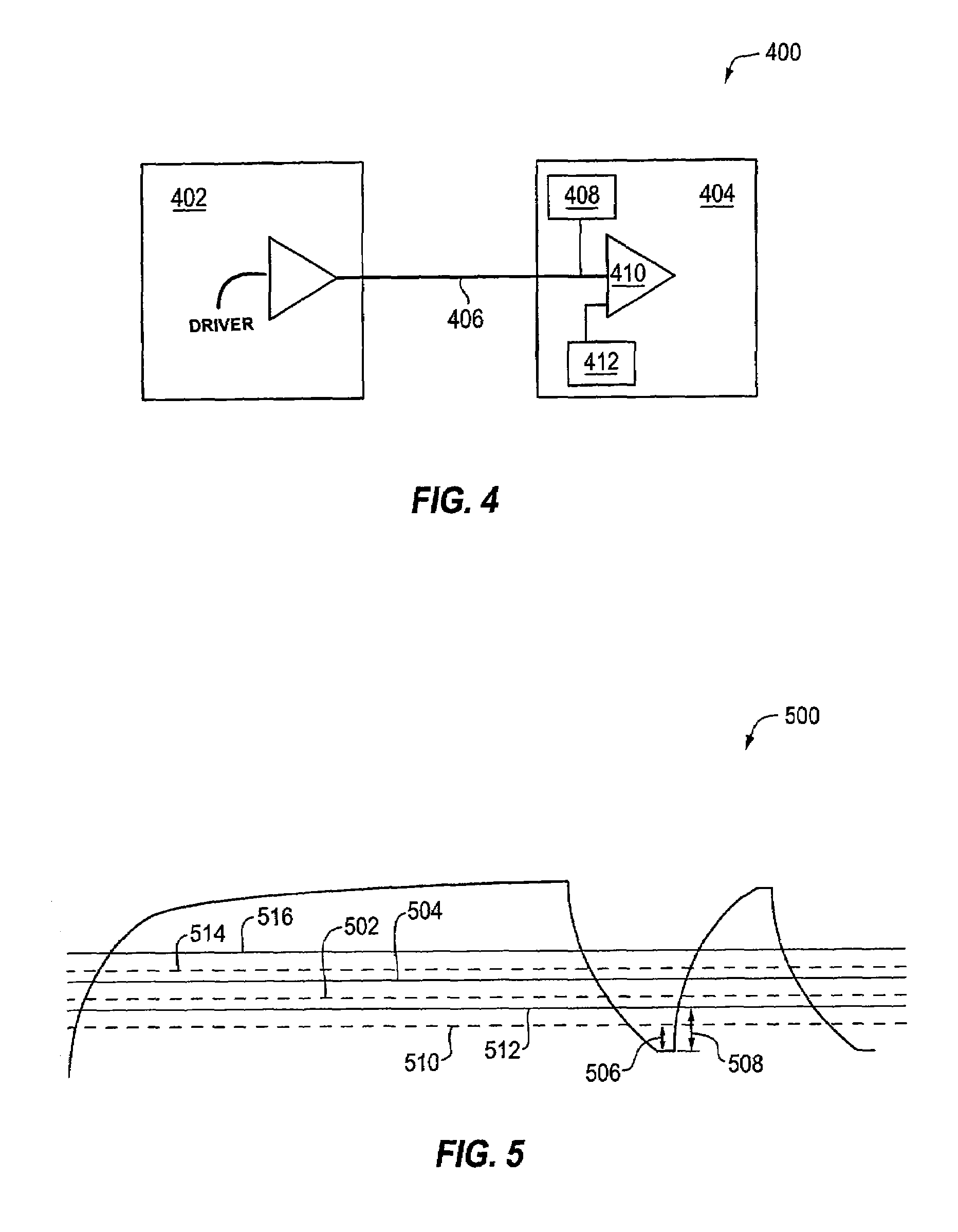
[0026]FIG. 4 illustrates an exemplary chip-to-chip communication system 400 in accordance with an embodiment of the present invention. The communication system 400 inc...


PUM


Abstract

Disclosed are novel methods and apparatus for efficiently providing equalization in single-ended chip-to-chip communication. In an embodiment, a method of adjusting signal levels to provide improved communication between a sender device and a receiver device is disclosed. The method includes providing a plurality of voltage dividers. The plurality of voltage dividers may be coupled to each other to provide a reference voltage to the receiver device. The method further includes providing a storage device to store previously received data by the receiver device and providing a controller to selectively activate the plurality of voltage dividers.

Description

FIELD OF INVENTION[0001]The present invention generally relates to the field of communication. More specifically, an embodiment of the present invention provides a technique for equalization in single-ended chip-to-chip wireline communication.BACKGROUND OF INVENTION[0002]Chip-to-chip wireline communication consists of a chip sending and receiving data from another chip over wires incorporated on a board on which the communicating chips are placed. The sending chip drives the data onto the wire, otherwise known as a board trace, using a driver circuit. The receiving chip receives the data at the other end of the communication bus using a receiver circuit. The unit of data transferred may be called a bit. A chip may use a single wire to send data, wherein the communication method is called single-ended signaling, or it may use a pair of wires to send data, wherein the communication method is called differential signaling.[0003]In single-ended signaling, a bit is driven onto a board tr...

Claims


Application Information

Patent Timeline
Patent Type & Authority Patents(United States)
IPC IPC(8): H03K5/159G11C7/10
CPCG11C7/1048G11C2207/2254
Inventor ROY, ANINDA
Owner ORACLE INT CORP
Why Eureka
Try Eureka