Eureka AIR delivers breakthrough ideas for toughest innovation challenges, trusted by R&D personnel around the world.

Self-aligning roller bearing

a self-aligning, roller bearing technology, applied in the direction of rotary bearings, rolling contact bearings, shafts and bearings, etc., can solve the problems of negative skew exerting a bad influence on the lifetime enhancement of the bearing, the increase in the index of cleanliness of materials does not have a noticeable effect on the lifetime enhancement, and the surface initiated failure of the bearing, etc., to achieve the effect of suppressing the rotation slip of the roller, reducing the coefficient of friction of the outer ring ra

Inactive Publication Date: 2008-10-14
NSK LTD
View PDF15 Cites 4 Cited by
  • Summary
  • Abstract
  • Description
  • Claims
  • Application Information

AI Technical Summary

Benefits of technology

[0014]The present invention has been made in view of above respects, and it is an object of the present invention to provide a self-aligning roller bearing capable of achieving an extension of the lifetime by suppressing an early flaking caused due to the surface damage such as the peeling, or the like.
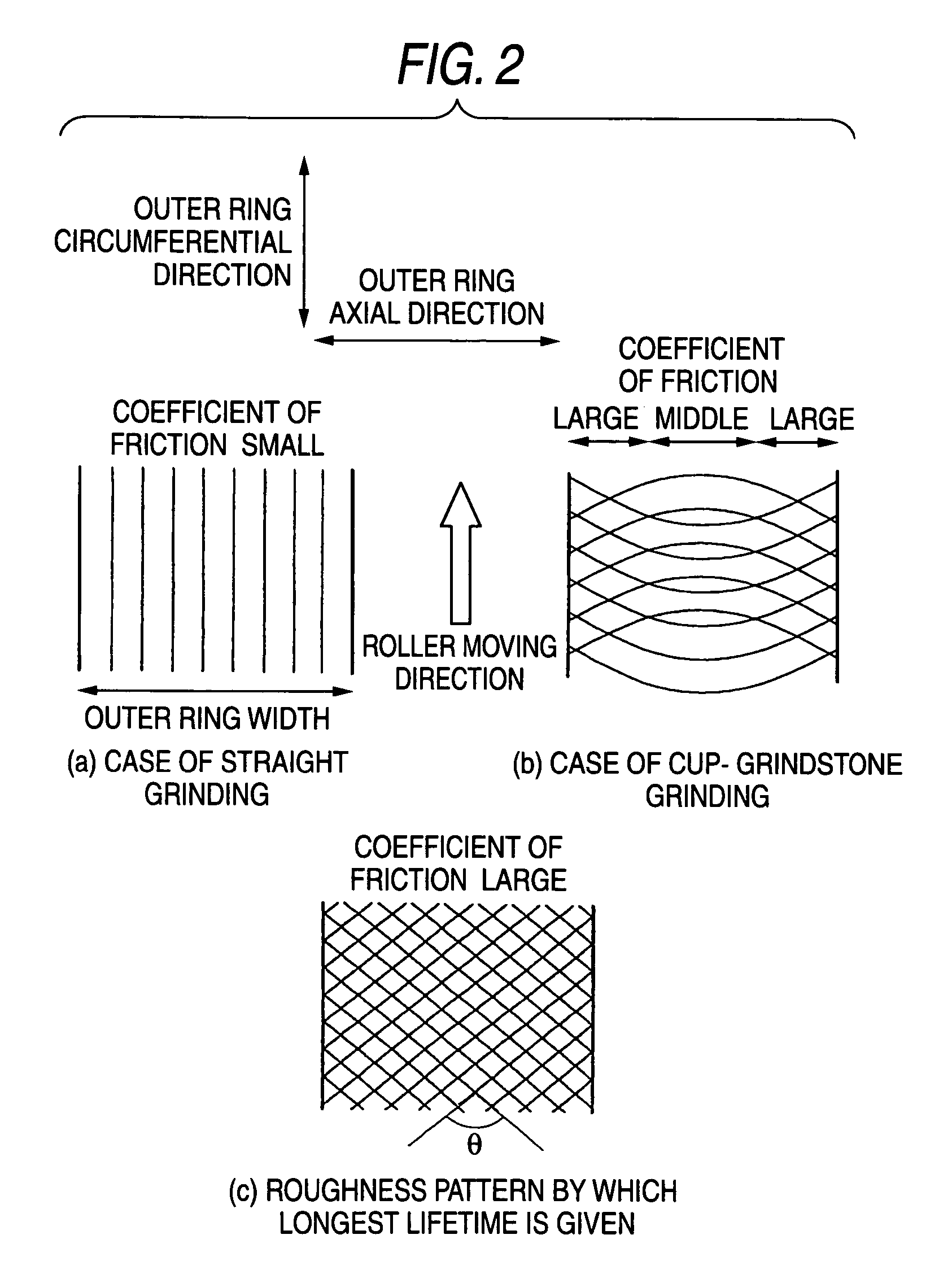
[0028]According to the first self-aligning roller bearing of the present invention, a local variation of the roughness can be reduced in the overall range of the outer ring raceway surface that comes into contact with the roller, and the coefficient of friction of the outer ring raceway surface to the roller can be stably increased. Therefore, the rotation slip of the roller can be suppressed and also the early flaking caused due to the surface damage such as the peeling, or the like can be suppressed, whereby the extension of the lifetime can be achieved.
[0029]Also, because the roughness parameter S of the outer ring raceway surface is set within 0<S≦20 μm, the coefficient of friction at the contact portion between the outer ring raceway surface and the roller can be increased, and the slip of the roller can be suppressed. Therefore, the early flaking caused due to the surface damage such as the peeling, or the like can be suppressed, and thus the lifetime enhancement of the self-aligning roller bearing can be achieved.
[0030]Also, according to the second self-aligning roller bearing of the present invention, for the purpose of suppressing the tangential force acting on the inner ring and the rolling element and acting as the flaking cause of the self-aligning roller bearing, the average roughness of the rolling contact surface of the rolling element is set to Ra<0.1 μm, the average roughness of the inner ring raceway surface is set to Ra<0.15 μm, and the average roughness Ra of the outer ring raceway surface is set within 0.1 μm≦Ra≦0.5 μm. Therefore, generation of the minute plastic flow on the inner ring raceway surface can be suppressed, and thus the stable lifetime enhancement can be attained.
[0031]In addition, according to the third self-aligning roller bearing of the present invention, if the roughness of the outer ring is increased by setting the hardness of the roller as the rolling elements harder than the raceway rings and leaving the retained austenite, the minute slip on the inner ring can be suppressed and thus the surface fatigue of the inner ring can be reduced, but the roller becomes the portion that is most susceptible to the surface fatigue. Based on this phenomenon, the lifetime can be prolonged by applying the material specification that is resistant to the surface fatigue to the rollers that are liable to be subjected to the fatigue. It is very effective for such surface damage such as the peeling, or the like to enhance the surface hardness of the rolling elements as well as to leave the retained austenite.

Problems solved by technology

However, unlike the above bearings, in some cases the surface initiated failure is caused in the self-aligning roller bearing according to the application condition.
This surface initiated failure signifies that the minute plastic flow is generated on the surface of the inner ring in the clean environment and then the peeling crack is generated and spread from there to lead to the flaking.
As a result, an increase in the index of cleanliness of material does not have a noticeable effect on the lifetime enhancement of the self-aligning roller bearing.
Also, it is concluded that, since a negative skew to incline the rolling elements to the inside of the bearing increases the axial load, such negative skew exerts a bad influence upon the lifetime of the bearing.
However, when the roughness of the outer ring raceway surface is made simply larger than that of the inner ring raceway surface, in some cases either the negative skew is ready to occur or the lifetime is prolonged even though the negative skew is increased.
Therefore, it is hard to say that the skew control has a critical effect on an extension of the lifetime.
Also, in case the roughness of the outer ring raceway surface is made excessively large, unevenness of the outer ring raceway surface becomes larger than a thickness of the oil film.
Therefore, the lubrication condition is worsened and conversely the lifetime of the bearing is liable to become short.
In the situation that the machining condition is not good when viewed in the light of the roughness range, if there exist the portions at which the surface roughness is reversed between the inner ring raceway surface and the outer ring raceway surface because the roughness range of the inner ring raceway surface and the roughness range of the outer ring raceway surface come very close to each other or overlap with each other, a frictional force generated at the contact portions between the rolling elements and the inner and outer rings is varied and then the rotation of the rollers becomes unstable.
Thus, the minute slip is generated at the contact portions between the inner ring and the rolling elements, and also the surface damage such as the peeling, or the like is prone to occur.
Therefore, it is not enough just to make the surface roughness of the outer ring raceway surface larger than that of the inner ring raceway surface.
This high temperature tempering process can cause the retained austenite to decompose, but such process exerts the harmful effect such that the hardness is lowered.
As a result, the fatigue of the roller surface makes progress considerably.

Method used


Image

  • Self-aligning roller bearing
  • Self-aligning roller bearing
  • Self-aligning roller bearing

Examples


first embodiment

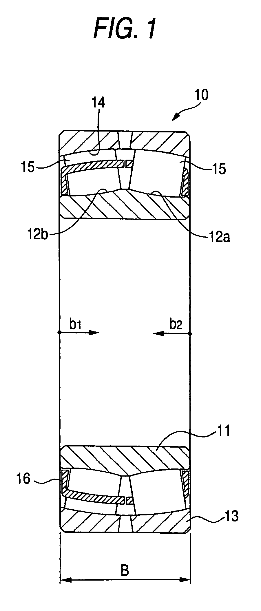
[0056]the present invention will be explained with reference to FIGS. 1 to 12 hereinafter.

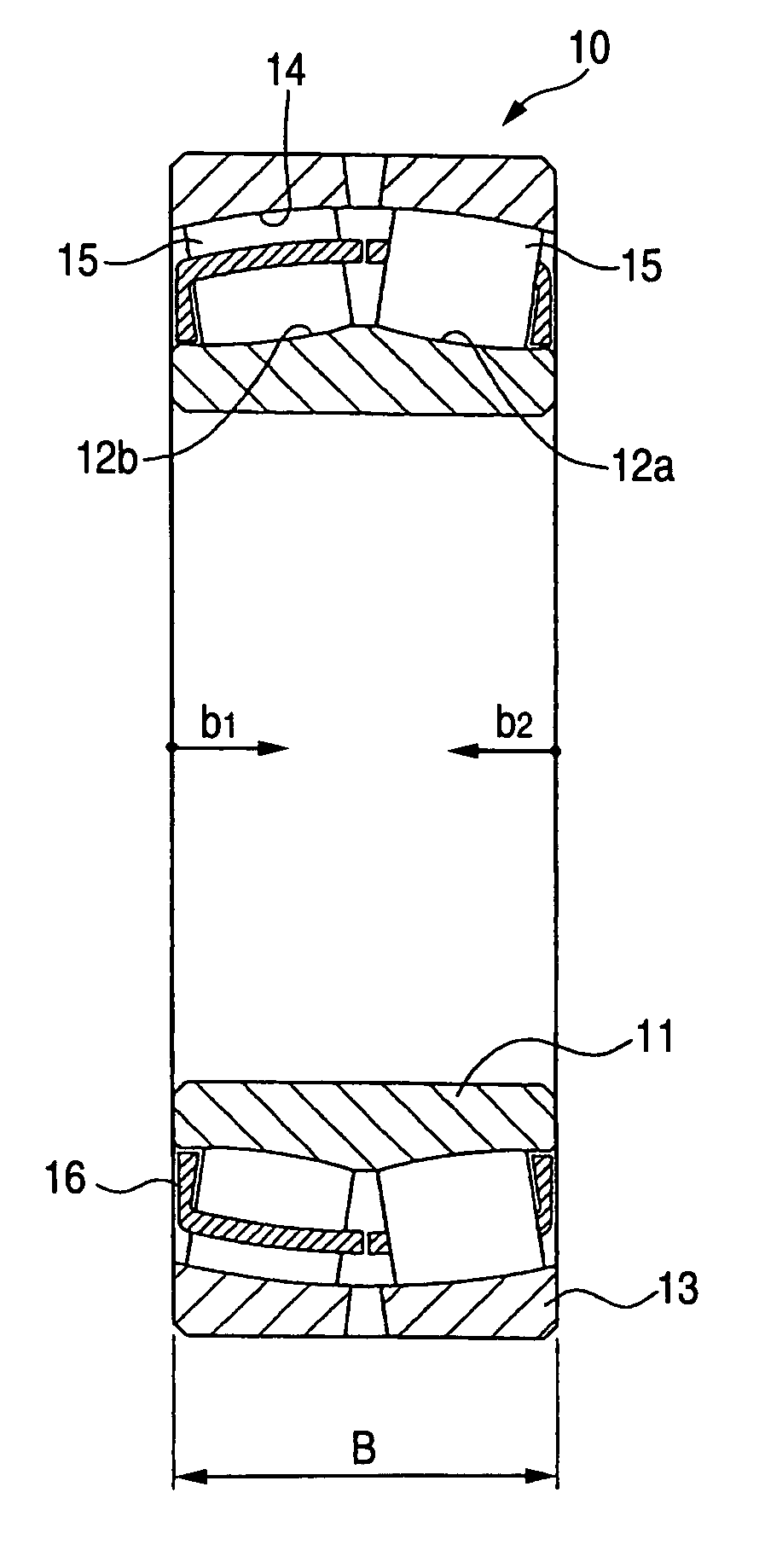
[0057]FIG. 1 is an axial sectional view of a self-aligning roller bearing according to a first embodiment of the present invention. In FIG. 1, a self-aligning roller bearing 10 according to the first embodiment of the present invention has an inner ring 11. Double row raceways (also referred to as “inner ring raceway surfaces” hereinafter) 12a, 12b are formed on an outer peripheral surface of the inner ring 11 along the circumferential direction of the inner ring 11. Also, the self-aligning roller bearing 10 has an outer ring 13. A double row integral spherical raceway (also referred to as an “outer ring raceway surface” hereinafter) 14 is formed on an inner peripheral surface of the outer ring 13 along the circumferential direction of the outer ring 13.

[0058]The inner ring raceway surfaces 12a, 12b and the outer ring raceway surface 14 are opposed to each other. A plurality of rollers 15 are p...


PUM


Abstract

A roughness of an outer ring raceway surface 14 formed on an inner peripheral surface of an outer ring 13 is made larger than a roughness of inner ring raceway surfaces 12a, 12b of an inner ring 11. Also, an average roughness Ra of the outer ring raceway surface 14 is set within 0.1 μm≦Ra≦0.5 μm in an axial direction and a circumferential direction in ranges of b1 / (B / 2)≦0.9, b2 / (B / 2)≦0.9 and in a measured length of 0.1 mm to 1.0 mm where B is a width of the outer ring 13 and b1, b2 are a distance from both end surfaces of the outer ring 13 in the axial direction respectively. A roughness parameter S of the outer ring raceway surface is set within 0<S≦20 μm.

Description

TECHNICAL FIELD[0001]The present invention relates to lifetime enhancement of a self-aligning roller bearing used in a general industrial machinery, a machine tool, a vibrating screen, steel industry, a motorcycle engine, and so forth.BACKGROUND ART[0002]The self-aligning roller bearing has the advantage of capable of preventing the generation of abnormal load and increasing the radial load capacity because a contact condition of the rolling elements is not varied even when the outer ring or the inner ring is inclined due to a fitting error or an impact load. For this reason, the self-aligning roller bearing is used widely as various roll neck bearings in the papermaking machine, the vehicle bearing, various industrial bearings, and so on.[0003]By the way, the normal ball bearing or cylindrical roller bearing is broken down by the subsurface initiated facture in a clean environment in which an oil film is satisfactorily formed. This subsurface initiated facture signifies that the fa...

Claims


Application Information

Patent Timeline
Patent Type & Authority Patents(United States)
IPC IPC(8): F16C23/08F16C33/58
CPCF16C23/086F16C33/64F16C33/585F16C2240/42F16C19/38F16C2240/54F16C23/08F16C33/58F16C33/34
Inventor UEDA, KOUJIUEDA, TOHRU
Owner NSK LTD
Why Eureka
Eureka Blog
Learn More