Planar membraneless microchannel fuel cell

a microchannel fuel cell, membraneless technology, applied in the direction of fuel cell details, aqueous electrolyte fuel cells, electrochemical generators, etc., can solve the problems of high cost associated with rechargeable batteries, and inability to meet the goals of rechargeable batteries alon

Inactive Publication Date: 2008-10-14
CORNELL RES FOUNDATION INC
View PDF11 Cites 19 Cited by
  • Summary
  • Abstract
  • Description
  • Claims
  • Application Information

AI Technical Summary

Benefits of technology

[0045]FIG. 1 is a drawing 100 showing a schematic sectional side view of a planar microfluidic membraneless micro-fuel cell, which is not to scale. In the embodiment depicted in FIG. 1, a flow cell 110 comprises two inlets 112, 114, which provide entry for two fluids. As is explained hereinbelow, the two fluids can be a fuel and an oxidizer that react to produce electrical power if the cell is to be used as a fuel cell, the two fluids can comprise substances that react as a result of applied electrical signals (for example in an electrochemical cell), or the two fluids can be fluids that carry substances that react chemically in the absence of an applied electrical signal (and therefore do not require the presence of electrodes). If the flow cell is constructed from a material that is transparent in a region of the electromagnetic spectrum, reactions conducted therein can be driven by applied optical illumination (e.g., ultraviolet, visible, and / or infrared radiation) that falls in the region of transparency, or using more generally electromagnetic radiation of any wavelength at which the wall material is transparent. In addition, electromagnetic radiation generated within the flow cell can be utilized outside the flow cell if the wall material is transparent at the wavelength of such electromagnetic radiation. While the present discussion describes a system using two fluids, systems using a plurality of fluids that operate according to the principles of the invention are contemplated.

Problems solved by technology

Such goals can only be met by a combination of rechargeable batteries and fuel cells.
One of the most challenging aspects of the miniaturization of fuel cells is the PEM, which suffers from numerous problems including: drying out of the membrane (especially at high operating temperatures), fuel crossover into the oxidizer, in addition to the high expense typically associated with membrane development.
All of these problems are further compounded by the need to decrease the thickness (further increasing the complication of the network structure) of the PEM when designing a micro-fuel cell.
While these enzymatic redox systems can provide the desired selectivity, they typically generate very low power and suffer from all of the problems attendant to the use of enzymes, with long-term stability being especially problematic.
The PEM also takes up much of the space in the non-enzymatic micro-fuel cells being developed, thus limiting the size of the final device.
Despite the significant advances in PEM fuel cells that have been achieved in the last decade, there are still a number of unresolved issues that have limited their use.
The polymer electrolyte membrane is an expensive and often unreliable component of PEM fuel cells.
Thus, one of the more serious complicating factors (among numerous others) in the miniaturization of fuel cells has been the instability, under operating conditions, of the membrane electrode assembly, which incorporates the proton exchange membrane.
However, the complicated evaporation techniques necessary, fabrication limitations, as well as the lack of versatility of this micro-fuel cell platform make this design somewhat impractical.
The only way to increase the interface area is by increasing channel depth (which may be difficult or costly to achieve using certain manufacturing techniques such as photolithography [which has difficulty producing large vertical walls] or to do without at the same time increasing channel length) or channel length (the maximum useful length may be limited by the dynamics of parallel and laminar flow.
Since the amount of a substance that can be caused to react is proportional to the area, of the interface between the two laminar flows, one problem that needs to be solved is how to arrange for larger areas of the interface between such laminar flows and also to increase the interface area without also increasing the volume of fluid.

Method used


Image

  • Planar membraneless microchannel fuel cell
  • Planar membraneless microchannel fuel cell
  • Planar membraneless microchannel fuel cell

Examples


Embodiment Construction

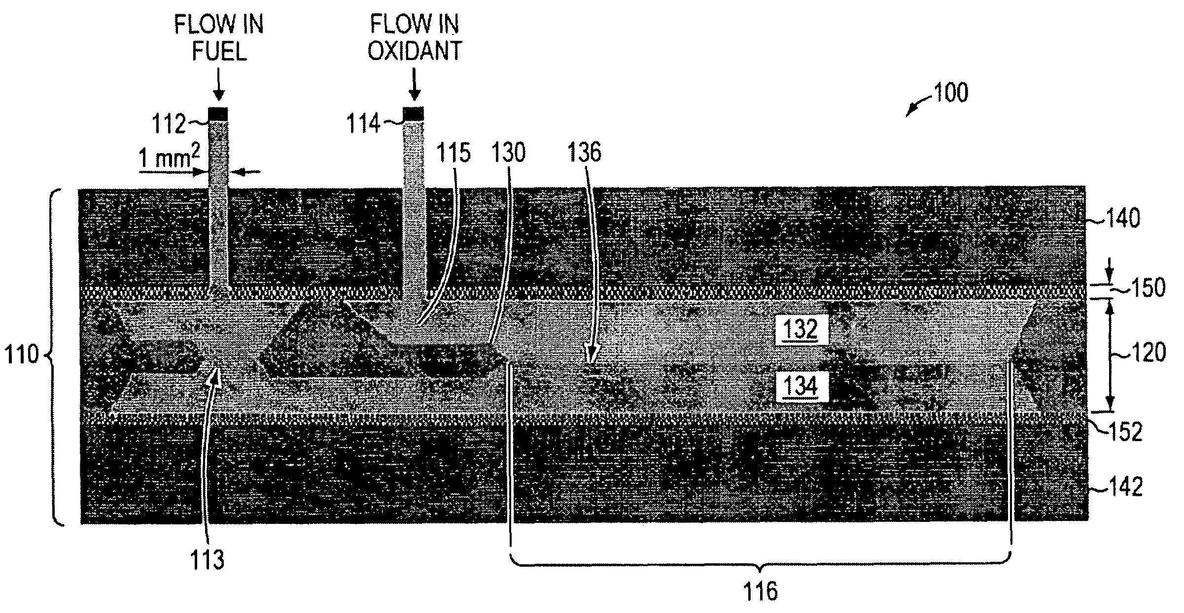
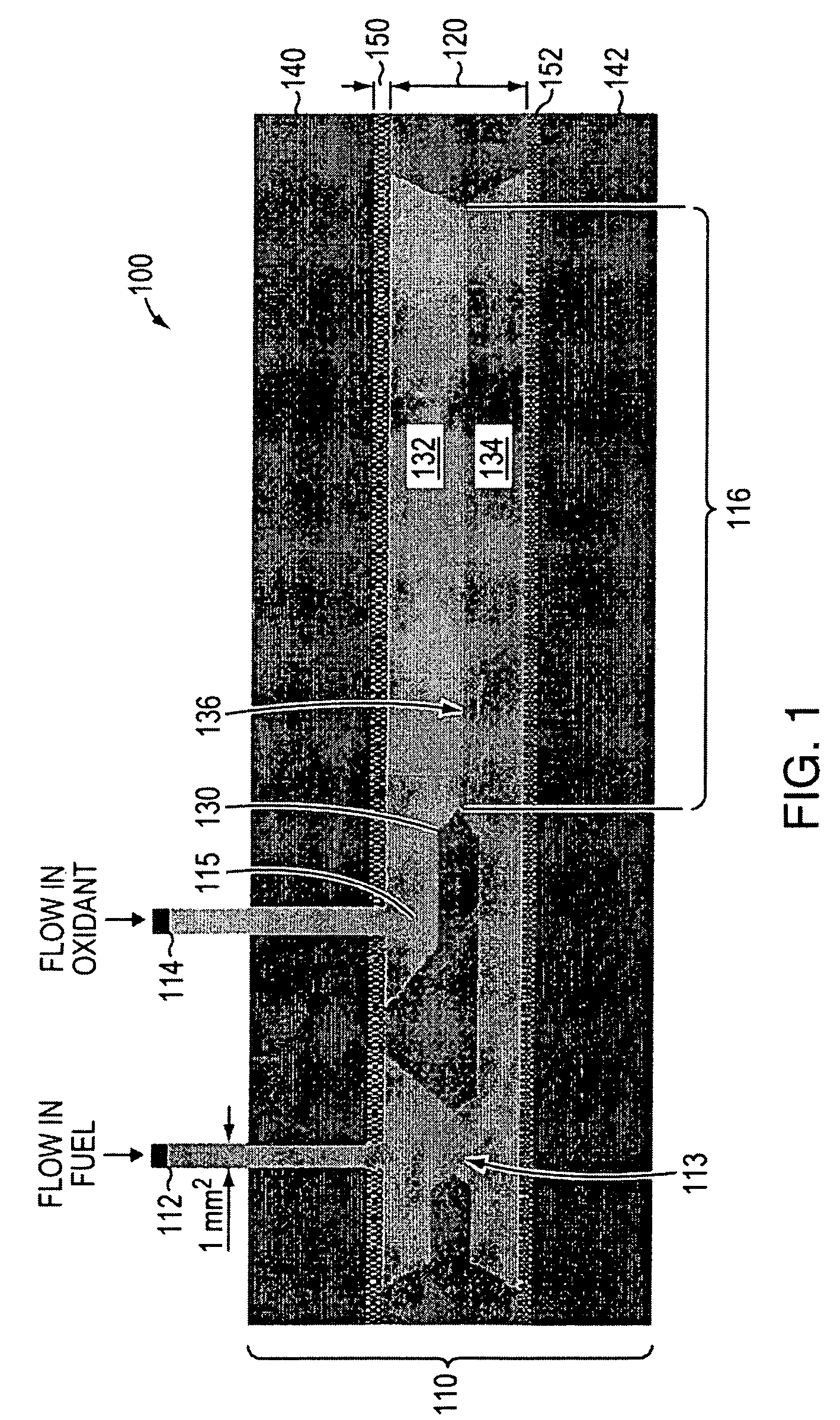
[0038]The invention described herein relates to a planar membraneless microchannel structure. In one embodiment, the structure is useful in constructing a planar membraneless microchannel fuel cell (PM2FC) and for generating electrical power by consuming fuel components (e.g., a substance capable of being oxidized and a substance capable of being an oxidizer) within the structure so that the fuel components are reacted and electrical power is produced that can be extracted from terminals of the fuel cell embodying the planar membraneless microchannel structure. However, the features of the planar membraneless microchannel structure described hereinbelow are also useful in other applications. Examples of other applications include certain kinds of diffusion controlled chemical reactions and applications of those reactions, such as in diagnostic tests; and controlled processing of materials, based on controlled fluid dynamics.

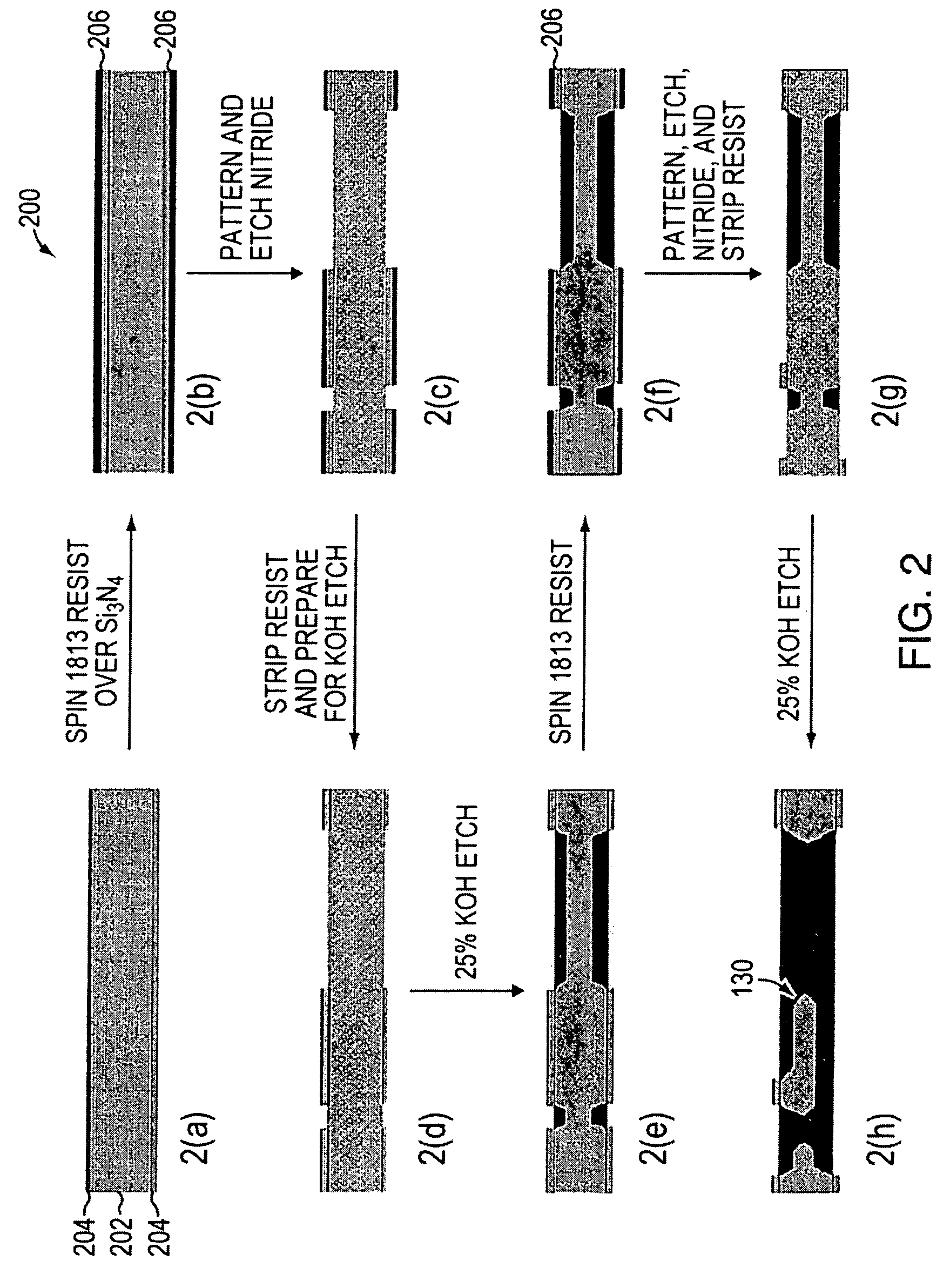
[0039]The flow regime described by The '206 patent provides...


PUM

PropertyMeasurementUnit
weightaaaaaaaaaa
depth×1aaaaaaaaaa
depth×1aaaaaaaaaa

Abstract

A planar microfluidic membraneless flow cell. The design eliminates the need for a mechanical membrane, such as a polyelectrolyte membrane (PEM) in a fuel cell, by providing a flow channel in which laminar flow regimes exist in two fluids flowing in mutual contact to form a “virtual interface” in the flow channel. In the flow cell, diffusion at the interface is the only mode of mass transport between the two fluids. In a fuel cell embodiment, a planar design provides to large contact areas between the two streams, which are fuel and oxidant streams, and between each stream and a respective electrode. In some embodiments, silicon microchannels, of fixed length and variable width and height, have been used to generate power using formic acid as fuel and oxygen as oxidant. Power densities on the order of 180 μW / cm2 have been obtained using this planar design.

Description

CROSS-REFERENCE TO RELATED APPLICATIONS[0001]This application claims priority to and the benefit of U.S. provisional patent application Ser. No. 60 / 579,075, filed Jun. 10, 2004, entitled “Planar Membraneless Microchannel Fuel Cell,” and claims priority to and the benefit of U.S. provisional patent application Ser. No. 60 / 629,440, filed Nov. 19, 2004, entitled “Planar Membraneless Microchannel Fuel Cell,” which applications are incorporated herein by reference in their entirety.STATEMENT REGARDING FEDERALLY FUNDED RESEARCH OR DEVELOPMENT[0002]The invention described herein was made in the performance of work under Army Research Office contract DAAD19-03-C-0100, under NSF contract ACT-0346377, and under NSF Grant ECS-0335765, and is subject to the provisions of Public Law 96-517 (35 U.S.C. §202) in which the Contractor has elected to retain title.FIELD OF THE INVENTION[0003]The invention relates to microfluidic flow cells in general and particularly to a microfluidic flow cell that pr...

Claims


Application Information

Patent Timeline
Patent Type & Authority Patents(United States)
IPC IPC(8): H01M8/04
CPCH01M8/006H01M8/026H01M8/0289H01M8/04082H01M8/04186H01M8/08H01M8/083H01M8/086Y02E60/50H01M8/04
Inventor COHEN, JAMIE LEEVOLPE, DAVID JAMESWESTLY, DARON A.PECHENIK, ALEXANDERABRUNA, HECTOR D.
Owner CORNELL RES FOUNDATION INC
Why Eureka
Try Eureka