
Video device and method for synchronising time bases of video devices

Active Publication Date: 2008-10-14
GRASS VALLEY CANADA
View PDF10 Cites 7 Cited by
  • Summary
  • Abstract
  • Description
  • Claims
  • Application Information

AI Technical Summary

Benefits of technology

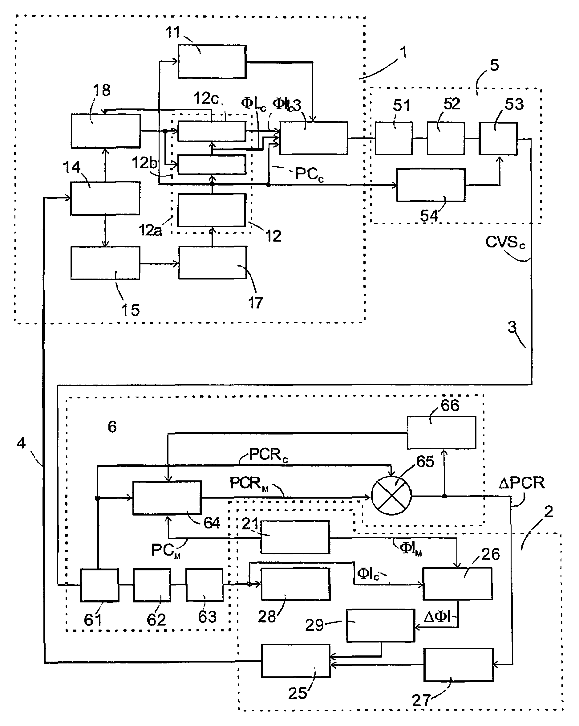
[0031]Preferably, a time for carrying out step d) is chosen according to the phase difference determined in step b) such that after carrying out step d) the video signal at the first device assumes a predefined phase, preferably the beginning of an image in the video signal. In this way, a discontinuity of the image information received by the second video device can be avoided.
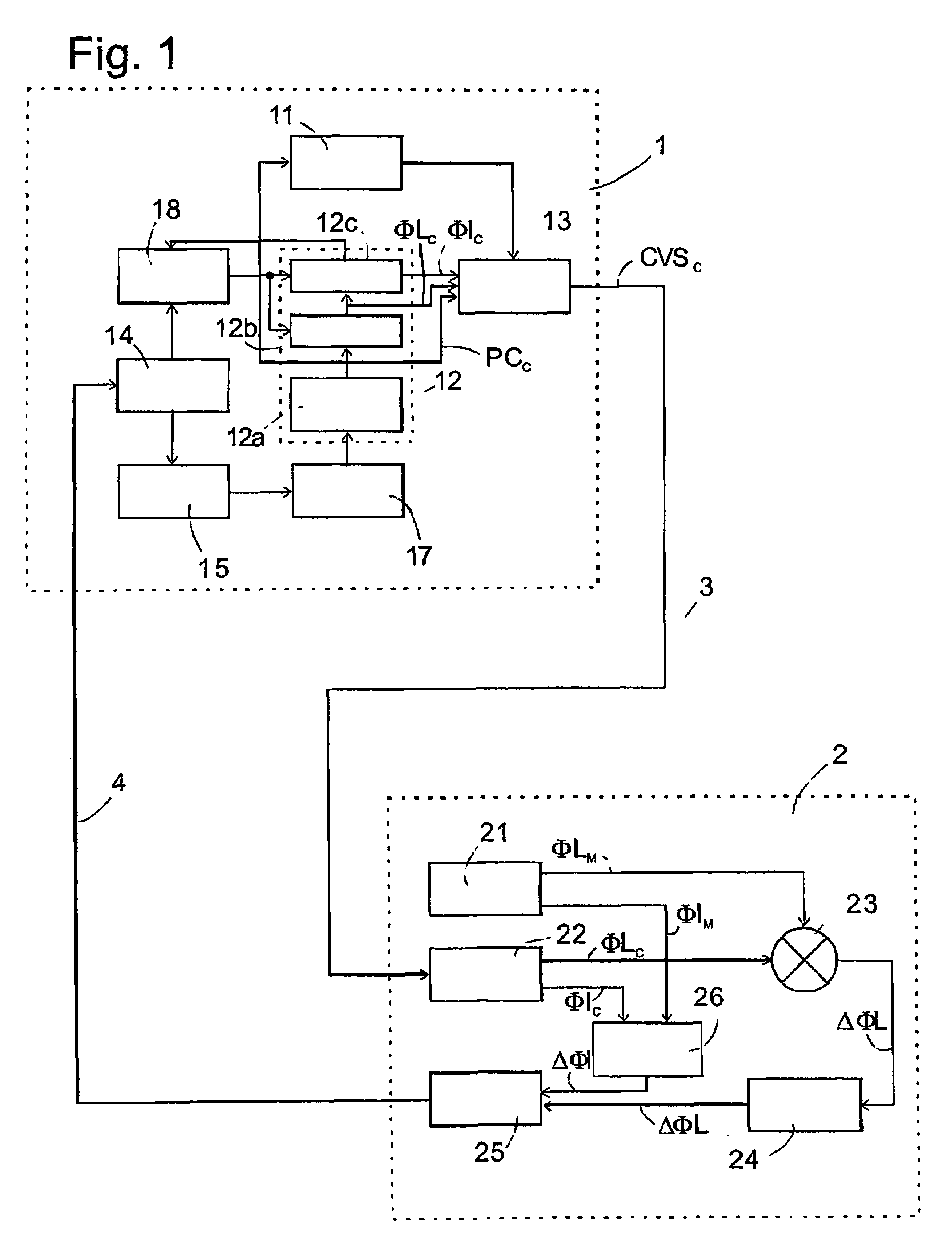
[0034]in the camera, the reverse operation is performed, and the approximate H phase difference is applied to a digital filter (PI), resulting in a control signal which will be either converted in analogue domain or control a Direct Digital Synthesizer. On both cases the clock generation of the first device will shift up (or down) its frequency, reducing (or increasing) its line and frame duration until the H phase difference is cancelled. Three advantages of this technique appear first, the transmission rate of the H phase difference can be much lower than its analogue counterpart; second, it is totally protected against transmission noise; last, the transmission media may have even drop-outs since the latest digital control signal is always available.
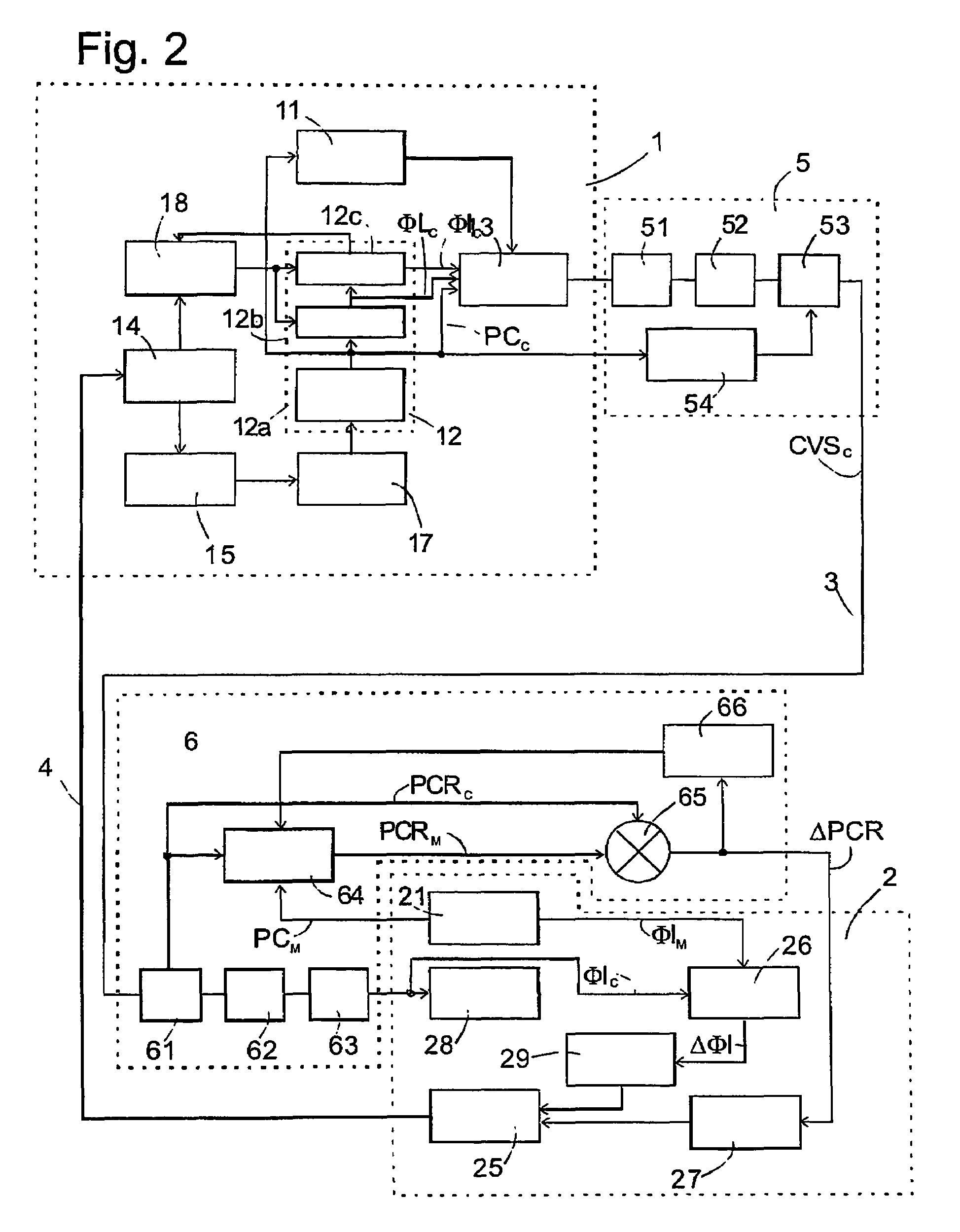
[0041]It also gets rid of the basic assumption to link pixel frequency control and H phase. In all synchronisation systems dealing with video sync pulses, the H phase PLL modifies the pixel frequency until the H phase is correct. This is due to the fact that H phase is the integral of the pixel frequency. It may result in very slow behaviour. The invention splits the pixel frequency control and (H&V) phase control into 2 separate processes, allowing much quicker locking time.

Problems solved by technology

If these time bases operate independently from one another, the pixel frequencies generated by these time bases will never be perfectly identical, no matter how high the level of precision of the time bases is.
The image synchroniser is versatile and easy to control, but it has a disadvantage in that it causes an unpredictable delay, which may take any value between 0 and 1 image.
Such a delay can be extremely embarrassing when mixing video and audio signals to produce the program content.
So called “lip sync” effects (audio signal leading or lagging video signal) are noticeable and unwanted effects.
Otherwise, the reset pulse may be too soon or too late resulting in an erratic permanently wrong time base sequence.
Furthermore, it relies also on a perfectly predictable transmission delay of the reset pulse.

Method used


Image

  • Video device and method for synchronising time bases of video devices
  • Video device and method for synchronising time bases of video devices
  • Video device and method for synchronising time bases of video devices

Examples


Embodiment Construction

[0052]In FIG. 1, the first video device is a camera 1, and the second video device is a receiving part (generally so called Base Station or Camera Control Unit) 2 which receives an analogue composite video signal from the camera 1 by a downlink transmission line 3, e.g. a coaxial wire, optical fiber, or wireless analogue transmission system, and sends video signal to the mixer (not shown) and control information to the camera 1 by an uplink transmission line 4, which may be a second coaxial wire, optical fibre, or wireless analogue transmission system. Although not shown, the mixer will generally have more than one input port for connecting a plurality of cameras or other sources of video signals by means of transmission lines which may vary in length and thus cause varying transmission delays between the image signal source and the CCU 2.

[0053]The camera 1 comprises an imager chip 11, e.g. a charge coupled device (CCD) onto which light from a scenery is incident and from which imag...


PUM


Abstract

A video system comprises a first video device which transmits a video signal comprising image information and synchronisation information and a second video device which receives the composite video signal. The second device has a time base. For synchronising the two devices synchronisation information is extracted from the video signal received by the second Video device and from the time base of the second video device; a phase difference between the video signal received by the second video device and the time base of the second video device is determined based on the extracted synchronisation information; control information of a first type representative of the amount of the phase difference is transmitted to the first device; and in the first device the phase of the video signal is switched by a phase angle represented by the first type control information.

Description

[0001]This application claims the benefit under 35 U.S.C. § 365 of European patent application No. 03290401.3 filed Feb. 18, 2003.FIELD OF THE INVENTION [0002]The present invention relates to a video device and to a method for synchronising time bases of a first video device which transmits a video signal and of a second video device which receives said video signal.[0003]The video signal can be a native video signal generated by the first video device and comprising image information and synchronisation information derived from the time base of said first video device (composite video signal). Alternatively, the video signal can be a compressed digital stream obtained from the native video signal through a compression engine at a clock rate that is generally fully asynchronous to the image generation clock. In this case, image synchronisation information derived from the native time base is lost and packet synchronisation is added, providing the synchronisation information of the v...

Claims


Application Information

Patent Timeline
IPC IPC(8): H04N9/475H04N5/04H04N5/95H04N5/073H04N5/232H04N5/268
CPCH04N5/04H04N5/073H04N5/23203H04N5/268H04N23/66
Inventor MOREL, PHILIPPEMALNOE, PASCALBELLANGER, DIDIER
Owner GRASS VALLEY CANADA
Learn More